Ever wondered why two aluminum profiles with identical dimensions perform completely differently in your application? The answer often lies in a single number that many engineers overlook: the extrusion ratio. This critical parameter shapes everything from grain structure to mechanical strength, yet it rarely gets the attention it deserves during the specification process.
The extrusion ratio for aluminum is the numerical relationship between the cross-sectional area of the original billet and the cross-sectional area of the finished extruded profile. It quantifies how much the aluminum is compressed and deformed as it passes through the die.
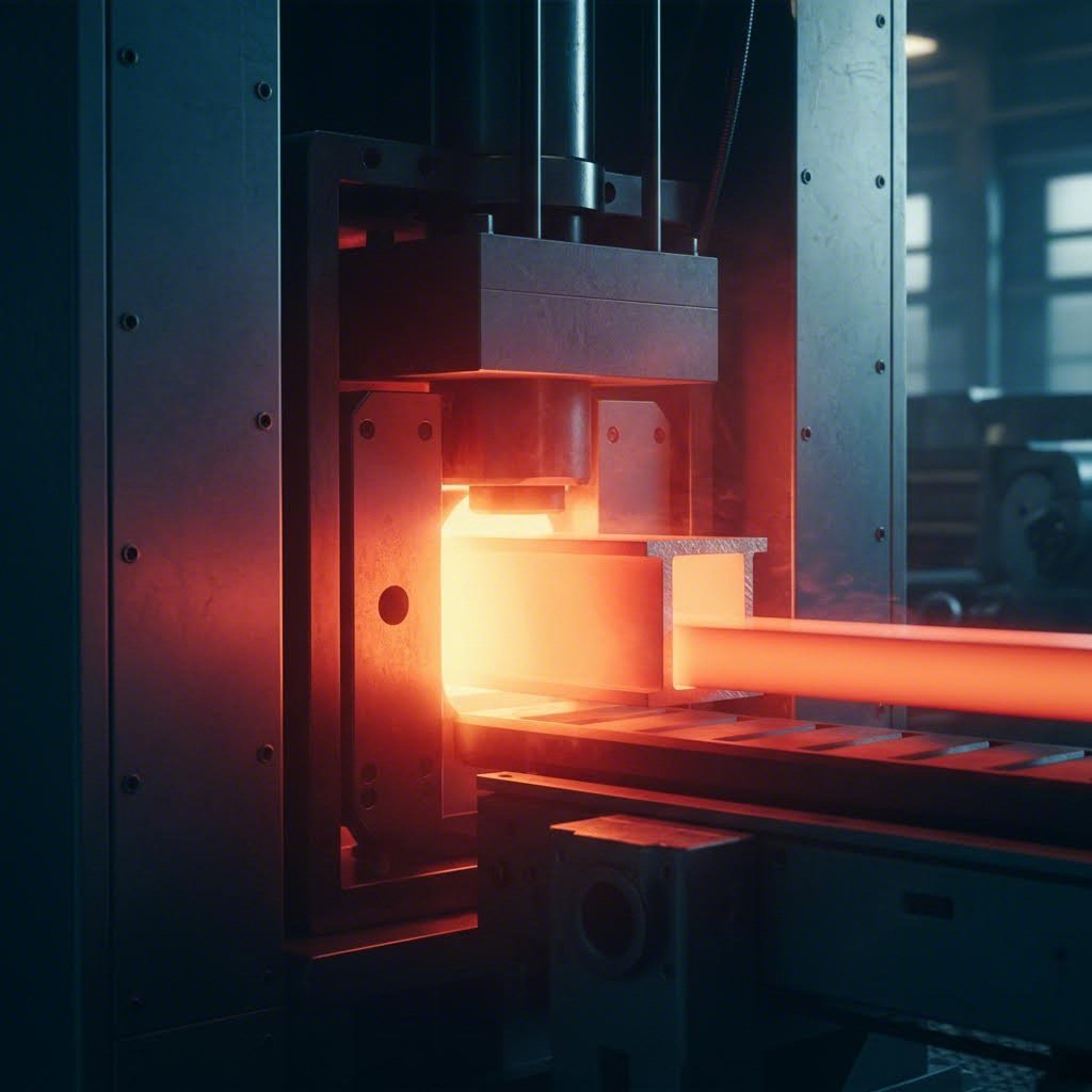
Understanding what is aluminum extrusion at a fundamental level means grasping this ratio. When you push a cylindrical aluminum billet through a shaped die opening, the metal undergoes severe plastic deformation. The meaning extrusion carries here directly relates to how dramatically the material transforms during this process.
The formula itself is straightforward:
Extrusion Ratio (ER) = Cross-sectional Area of the Billet ÷ Cross-sectional Area of the Profile
Let's break this down with a practical example. Imagine you're working with a solid cylindrical billet that has a cross-sectional area of 500 cm². If your finished profile has an area of just 5 cm², your extrusion ratio becomes 100:1. This tells you the aluminum has been forced to reduce its cross-section by a factor of 100—a transformation that fundamentally changes the material's internal characteristics.
For what is extruded aluminum in practical terms, this ratio typically ranges from as low as 10:1 for simple shapes to over 100:1 for complex, thin-walled profiles. The definition for extrusion parameters varies by application, but understanding this core calculation gives you the foundation for everything else.
Here's where theory meets real-world performance. According to research published in PMC, the extrusion ratio is one of the most important factors affecting the service performance of aluminum profiles. The study on 7003 aluminum alloy demonstrated that different ratios (9, 20, and 56) produced dramatically different microstructures and mechanical behaviors.
A higher extrusion ratio—typically above 20:1 for demanding applications—subjects the aluminum to greater deformation. This process:
The aluminium extrusion definition extends beyond simple shaping. It's a metallurgical transformation where intense deformation promotes finer, more uniform grain size. Following the Hall-Petch relationship in materials science, this directly increases yield strength.
For engineers specifying profiles, procurement professionals evaluating suppliers, and designers creating new products, this single number determines whether your profile will meet performance requirements—or fail unexpectedly in the field. The gap between academic theory and practical application closes when you recognize that selecting the right ratio isn't just about what the press can achieve; it's about what your specific application demands.
Not all aluminum alloys behave the same way under extrusion pressure. When you're selecting materials for aluminum alloy extrusion, understanding the specific ratio capabilities of each alloy series can mean the difference between a successful production run and costly defects. Yet surprisingly, this critical information remains scattered across technical literature without clear, actionable guidance.
The extrusion aluminum process varies dramatically based on the alloy's chemical composition. Each series brings unique characteristics that directly influence how much deformation the material can handle—and at what speed.
According to data from Mastar Metal's extrusion complexity guide, the relationship between alloy composition and achievable extrusion ratios follows predictable patterns. The table below consolidates ratio ranges, difficulty classifications, and practical applications for each major alloy family:
| Alloy Series | Typical Extrusion Ratio Range | Difficulty Level | Common Applications |
|---|---|---|---|
| 1xxx (99%+ Al) | Up to 500:1 | Easy | Chemical equipment, food handling, electrical conductors |
| 2xxx (Cu alloys) | 6:1 to 40:1 | Difficult | Aerospace components, high-strength structural parts |
| 3xxx (Mn alloys) | 6:1 to 60:1 | Easy to Moderate | Heat exchangers, condensers, decorative trim |
| 5xxx (Mg alloys) | 6:1 to 50:1 | Moderate to Difficult | Marine applications, pressure vessels, automotive panels |
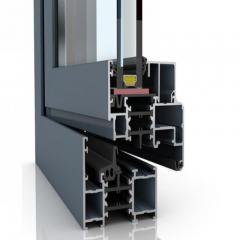
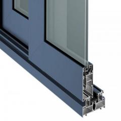
| 6xxx (Si+Mg alloys) | 30:1 to 100:1 | Easy | Architectural profiles, window frames, structural components |
| 7xxx (Zn alloys) | 6:1 to 30:1 | Difficult | Aerospace structures, high-performance sporting goods |
Notice the stark contrast between the 1xxx and 7xxx series. Pure aluminum alloys (1xxx) can achieve ratios up to 500:1 with exit speeds reaching 100 m/min. Meanwhile, high-strength 7xxx alloys like 7075 struggle to exceed 30:1, crawling along at just 1.5 to 5.5 m/min. This isn't just a minor difference—it's a fundamental limitation that affects production costs and feasibility.
When examining extrusion of aluminium alloys more closely, the 6xxx series stands out as the industry workhorse. Why? These alloys offer an exceptional balance of extrudability, mechanical properties, and surface finish quality.
Consider these specific alloy comparisons from industry data:
The aluminium alloy extrusion process becomes increasingly challenging as you move toward higher-strength materials. Alloys like 2024 and 7075 demand careful temperature control within a very narrow window—typically between 360-480°C. Push outside this range, and you'll encounter either excessive extrusion loads or unacceptable surface defects.
Temperature plays a crucial role in determining achievable ratios. For easy-to-extrude alloys like 6063, the working temperature range spans 480-520°C, providing considerable flexibility. In contrast, difficult alloys like 7075 require temperatures between 360-440°C, where the margin between the extrusion load limit and surface damage threshold becomes dangerously narrow.
What does this mean practically? When specifying extrusion aluminium profiles for demanding applications, you can't simply choose an alloy based on mechanical properties alone. The ratio you need for grain refinement must align with what that specific alloy can actually deliver. A 7075 profile requiring a 50:1 ratio simply isn't manufacturable—the physics won't allow it.
This interplay between alloy chemistry, temperature, and achievable ratios forms the foundation for calculating your specific profile requirements. Understanding how to work through these calculations systematically ensures you specify profiles that are both manufacturable and optimized for performance.
Ready to calculate your own extrusion ratio but not sure where to start? You're not alone. While the basic formula seems simple enough, the actual calculation process involves several steps that can trip up even experienced engineers—especially when dealing with complex hollow profiles. Let's walk through exactly how does extrusion work from a mathematical perspective.
Before diving into calculations, you'll need two fundamental measurements: the billet cross-sectional area and the profile cross-sectional area. According to engineering analysis from Michigan State University, the reduction (extrusion) ratio is defined as rx = Ao/Af, where Ao represents the original billet area and Af represents the final profile area.
Here's your systematic approach:
Sounds straightforward? The challenge comes in step three, where profile geometry can make calculations surprisingly complex.
Let's examine what is extruded from both solid and hollow profile perspectives, since each requires different calculation approaches.
Solid Profile Example: Imagine you're extruding a simple rectangular bar measuring 50 mm × 20 mm from a 150 mm diameter billet.
Hollow Profile Example: Now consider a square tube with outer dimensions of 40 mm × 40 mm and a 3 mm wall thickness, extruded from the same 150 mm billet.
Notice how the hollow profile produces a significantly higher ratio than it might first appear. This distinction matters because higher ratios demand greater extrusion pressure and more precise process control.
Understanding Aspect Ratio vs. Extrusion Ratio: Don't confuse these two terms. Aspect ratio describes a profile's geometric proportions—typically the ratio of width to height or the relationship between a feature's length and its thickness. Extrusion ratio, by contrast, measures the total material reduction during the forming process. A thin, wide profile might have a high aspect ratio (say, 20:1 width-to-height) but a moderate extrusion ratio (perhaps 35:1). Both affect manufacturability, but they measure entirely different characteristics.
Using CAD Software for Accurate Measurements: For complex profiles with curved surfaces, varying wall thicknesses, or intricate internal features, manual calculation becomes impractical. Modern CAD software provides precise area measurements through these steps:
Most CAD packages—including SolidWorks, AutoCAD, and Fusion 360—can calculate irregular profile areas to within 0.01 mm² accuracy. This precision becomes critical when you're working near the limits of what your selected alloy can achieve, as even small miscalculations can push you beyond manufacturable boundaries.
With your extrusion ratio calculated, the next consideration becomes whether your available press equipment can actually deliver the force required to achieve that ratio.
You've calculated your target extrusion ratio—but can your equipment actually deliver it? This question catches many engineers off guard. The relationship between press tonnage and achievable ratios isn't arbitrary; it follows predictable engineering principles that directly determine whether your profile is manufacturable.
Think of it this way: the extrusion press must generate enough force to overcome the aluminum's resistance to deformation. As your ratio increases, so does the required force. Push beyond your press capacity, and production simply stalls.
According to industry data from extrusion equipment manufacturers, extrusion force grows almost linearly with extrusion ratio for the same alloy and billet size. This means press capacity sets a hard ceiling on what ratios you can achieve.
How does aluminum extrusion work from an equipment perspective? The press forces heated billets through the die opening using hydraulic pressure measured in tons. Common industrial presses range from 500 tons to over 20,000 tons, with each size category suited to specific profile requirements.
Here's what happens when equipment and ratio requirements don't align:
The table below shows the practical relationship between press tonnage, billet specifications, and achievable extrusion ratios based on factory production data:
| Press Tonnage | Typical Billet Diameter | Max Circumscribed Circle | Practical Ratio Range | Typical Applications |
|---|---|---|---|---|
| 600T - 800T | 4" - 5" (102-127 mm) | 80-100 mm | 15:1 to 40:1 | Small architectural trim, simple solid profiles |
| 1000T - 1250T | 5" - 6" (127-152 mm) | 120-150 mm | 20:1 to 60:1 | Standard window/door frames, 6063 profiles |
| 1450T - 1800T | 6" - 7" (152-178 mm) | 150-200 mm | 25:1 to 80:1 | Industrial profiles, moderate complexity hollows |
| 2000T - 2500T | 7" - 9" (178-229 mm) | 200-280 mm | 30:1 to 100:1 | Large structural sections, harder alloys (6061, 6082) |
| 3000T - 5500T+ | 9" - 16" (229-406 mm) | 280-450 mm | 40:1 to 120:1+ | Heavy industrial, aerospace, complex multi-void hollows |
Understanding how is extruded aluminum made helps clarify why profile complexity directly affects tonnage requirements. Hollow profiles with multiple cavities require significantly more force than solid shapes—often 15-50% more according to extrusion engineering studies.
Exit speed provides another critical constraint. Easy-to-extrude 6063 alloys can achieve speeds up to 100 m/min on properly sized equipment. However, attempting high ratios on undersized presses forces dramatic speed reductions—sometimes to just 0.6-5 m/min for difficult alloys. This speed reduction directly impacts production economics.
When selecting equipment based on your target extrusion ratio, consider these practical guidelines:
Real-world experience reinforces these guidelines. According to production surveys, factories that upgraded from 1250T to 1450T presses reduced die repair frequency by 34% and increased extrusion speed for 6063 alloys by 18%. The additional tonnage provided more stable metal flow and lowered die-bearing stress.
What does this mean for your aluminum extrusion tooling decisions? If you're designing profiles that push ratio limits, verify that your supplier operates presses with adequate capacity—not just for initial production, but with headroom for process variations. Equipment capability becomes even more critical when considering how the extrusion ratio affects downstream processes like surface treatment and finishing.
Your extrusion ratio doesn't just affect what happens inside the press—it fundamentally shapes how your aluminum extrusion material behaves in every downstream process. From anodizing uniformity to machining behavior, the ratio you select during profile design echoes through the entire manufacturing chain. Yet this critical connection rarely appears in specification discussions.
Here's why this matters: the extrusion of aluminium at different ratios produces dramatically different grain structures. According to Bonnell Aluminum's technical resources, when the extrusion ratio of a section is low (below 10:1), portions of the shape involving the largest mass of metal will have little mechanical work performed on them. The metallurgical structure approaches the as-cast condition with coarse grains. This coarse structure doesn't just weaken mechanical properties—it creates visible inconsistencies in surface treatments.
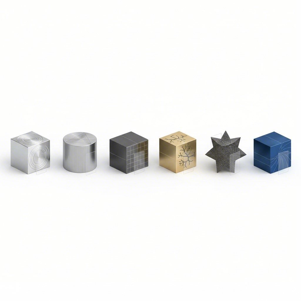
What are aluminum extrusions really made of at the microscopic level? The answer depends heavily on extrusion ratio. Higher ratios produce finer, more uniform grain structures through intense plastic deformation. This uniformity becomes visible when you anodize the surface.
Consider these downstream process implications:
Understanding how extruded aluminum is made helps explain why machining behavior varies so dramatically between profiles. The grain refinement from higher extrusion ratios affects chip formation, tool wear, and dimensional stability during CNC operations.
For applications demanding premium surface treatment results, target ratios above 25:1 minimum. When specifying profiles for architectural anodizing or visible painted finishes, pushing toward 40:1 or higher provides insurance against batch-to-batch finish variations. This proactive ratio selection during design prevents costly rejections at the finishing stage—where discovering grain structure problems is far too late to correct economically.
Of course, selecting the optimal ratio requires balancing these surface treatment considerations against your specific application requirements and design constraints.
You've learned what extrusion ratio means, how to calculate it, and which equipment can deliver it. But here's the question that really matters: what ratio should you actually specify for your specific project? Choosing wrong leads to expensive redesigns, production delays, or profiles that fail prematurely in service.
The challenge is that no single ratio works for every application. What are extrusions if not custom solutions tailored to specific performance requirements? Your optimal ratio depends on a complex interplay of mechanical demands, aesthetic standards, and economic realities. Let's build a practical framework for making this decision confidently.
Before specifying any ratio, you need clarity on your application's non-negotiable requirements. According to the Aluminum Extruders Council, every manufacturing process has practical limits—some designs prove very challenging to extrude, while minor tweaks can yield significant benefits in extrudability and lower costs.
Start by answering these fundamental questions:
Understanding what are extrusions capable of delivering at different ratios helps you match specifications to realistic manufacturing capabilities. According to aluminum extrusion design guidelines, poorly considered designs can lead to unnecessary material waste, higher costs, or profiles that fail to meet strength or assembly requirements.
Whether you're designing new aluminum profile extrusion specifications or evaluating supplier quotes, this comprehensive checklist prevents costly oversights:
Mechanical Property Requirements:
Dimensional Tolerance Considerations:
Surface Finish Needs:
Production Volume and Cost Optimization:
When to Push Ratio Limits:
Aggressive ratios (above 60:1) make sense when you need maximum grain refinement for critical structural applications, premium surface finish quality for architectural visibility, or enhanced mechanical properties that justify higher production costs.
When to Stay Conservative:
Moderate ratios (20:1-40:1) are appropriate when your alloy has limited extrudability (2xxx, 5xxx, or 7xxx series), profile complexity already challenges die design, cost optimization matters more than peak performance, or your supplier's press capacity limits options.
For design engineers defining aluminum extrusion specifications, this checklist transforms subjective decisions into systematic analysis. For procurement professionals evaluating types of aluminum extrusion suppliers, it provides clear criteria for assessing whether quoted capabilities actually match your requirements.
Remember: what is an aluminum extrusion ultimately depends on the choices you make during specification. Investing time in ratio optimization now prevents the frustration of discovering quality problems after tooling is cut and production has started. Yet even perfect ratio selection can be undermined if die design constraints aren't properly addressed—a topic that deserves careful attention.
You've calculated the perfect extrusion ratio for your application, verified press capacity, and specified the ideal alloy. But here's a reality check that catches many engineers by surprise: the die itself can become the limiting factor that prevents you from achieving your target ratio. Understanding this constraint before finalizing your extrusion profile design saves weeks of frustrating back-and-forth with manufacturers.
The extrusion aluminium process isn't just about pushing metal through an opening—it's about controlling how that metal flows, distributes, and exits the die under extreme pressure. Die geometry directly determines whether your calculated ratio remains theoretical or becomes achievable in production.
Think of the die as a precision flow control device. Every geometric feature affects how aluminum moves through the system, and each feature imposes its own constraints on achievable ratios.
Die Bearing Length: The bearing is the parallel-walled portion of the die opening that shapes the final extrusion profile. According to die design specialists, a decrease in bearing length results in increased material flow. Longer bearings slow metal flow and increase friction, which raises extrusion pressure requirements. When you're already pushing ratio limits, excessive bearing length can push required forces beyond press capacity.
Pocket Design: Pockets are relief areas machined behind the bearing that control metal flow distribution. Proper pocket geometry ensures uniform velocity across the entire profile cross-section. Poorly designed pockets create uneven flow that causes profile distortion—forcing you to reduce extrusion ratio to maintain dimensional stability.
Flow Balancing: Achieving uniform exit velocity across profiles with varying wall thicknesses requires careful flow balancing. Thicker sections naturally flow faster than thin walls. Die designers adjust bearing lengths and pocket depths to equalize flow rates, but extreme wall thickness variations (ratios exceeding 2:1) make balancing increasingly difficult at higher extrusion ratios.
The Circumscribing Circle Diameter (CCD) adds another constraint. According to technical documentation, larger CCD values increase extrusion force and cost. Even if your calculated ratio seems achievable, an oversized CCD can push total force requirements beyond equipment limits.
Profile complexity introduces constraints that pure ratio calculations don't capture. The relationship between geometric features and practical limits determines whether your extrusion parts are truly manufacturable.
Consider these die design factors that constrain extrusion ratio:
A useful metric for quantifying these challenges is the die difficulty ratio—calculated as profile area divided by perimeter. This helps gauge how challenging a profile is to extrude and guides simplification efforts when your target ratio proves unachievable with your initial design.
Collaborating with Die Designers:
Early engagement between designers, die manufacturers, and extrusion plants is crucial. According to manufacturing experts, discussing manufacturability constraints during the design phase helps projects avoid costly rework and achieve shorter lead times.
When working with die designers to optimize your ratio within design constraints, consider these approaches:
Die wear also influences long-term ratio achievability. Optimized die design reduces premature cracking, lowers replacement frequency, and minimizes production downtime. A die that works perfectly at startup may drift out of tolerance after extended production runs, effectively reducing your achievable ratio over time.
The bottom line? Your target extrusion ratio exists within a system of constraints—press capacity, alloy characteristics, and die geometry must all align. When they don't, something has to give. Understanding die limitations upfront lets you make informed trade-offs rather than discovering problems after expensive tooling is already cut. And when problems do arise during production, knowing how ratio-related issues manifest helps you troubleshoot effectively.
Your extrusion ratio calculations looked perfect on paper. The die design passed review. Production started—and then defects appeared. Sound familiar? Understanding what is an extrusion problem versus a process control issue can save you weeks of trial-and-error troubleshooting and thousands of dollars in scrap.
The reality is that extruding aluminum at aggressive ratios pushes metal flow physics to their limits. According to extrusion engineering specialists, when any one factor reaches its limit, stable extrusion is no longer possible. Recognizing ratio-related symptoms early—and knowing exactly how to respond—separates efficient production from costly firefighting.
Not every surface blemish or dimensional deviation stems from extrusion ratio issues. But certain defect patterns point directly to ratio-related causes. Here's your diagnostic guide linking symptoms to their underlying ratio connections:
Understanding what is extrusions' failure modes helps you diagnose problems systematically rather than guessing at solutions.
Once you've identified a ratio-related defect, targeted corrective actions can often restore stable production without costly die modifications. The temperature-extrusion ratio relationship provides your primary adjustment lever.
For Surface Tearing at High Ratios:
For Dimensional Instability:
For Inconsistent Mechanical Properties:
Temperature Adjustment Guidelines:
The aluminium extrusion meaning of "optimal temperature" shifts based on your ratio target. Higher ratios generate more friction heat, requiring lower starting temperatures. According to process engineers, billet temperature controls flow stress—higher ratios require higher billet temperature, but only up to a point before surface defects appear.
For 6063 alloy at moderate ratios (30:1-50:1), target billet temperatures of 480-500°C. Push above 60:1, and reduce starting temperature to 460-480°C to compensate for deformation heating. For harder alloys like 6061 or 7xxx series, narrow your temperature window further—often just 20°C separates successful extrusion from defects.
When Process Adjustments Aren't Enough:
Sometimes ratio-related problems require design changes rather than process tweaks. If you've exhausted temperature and speed adjustments without success, consider these options:
The goal isn't achieving the highest possible ratio—it's achieving the ratio that delivers consistent quality at acceptable cost. Knowing when to push limits versus when to redesign separates experienced specification engineers from those still learning expensive lessons. With troubleshooting knowledge in hand, your next step is ensuring your extrusion supplier has the capabilities to execute your optimized specifications reliably.
You've mastered the calculations, understood the alloy constraints, and troubleshot the common problems. But here's the final piece of the puzzle: none of this knowledge matters if your supplier can't actually deliver. Choosing the right extrusion partner determines whether your carefully optimized ratio specifications become reality—or remain theoretical ideals that fall apart in production.
So what is extrusion aluminum capability really about at the supplier level? It's not just equipment lists or certification logos. True capability means having the right combination of press diversity, technical expertise, and integrated services to handle whatever ratio challenges your project demands.
When you're asking what is aluminum extrusions suppliers can actually deliver, press capacity diversity becomes your first evaluation criterion. According to industry capability assessments, a supplier with multiple press capacities can handle a wider range of projects and maintain flexibility when production volumes change.
Here's why press range matters for ratio optimization:
A supplier operating only 1250T presses simply cannot deliver the 70:1 ratio your aerospace component requires—regardless of how impressive their quality certifications look. Conversely, running small profiles on oversized equipment wastes energy and often produces inferior results.
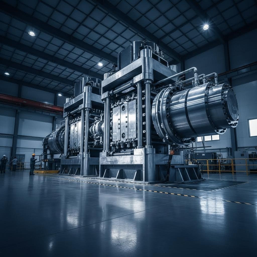
For example, Shengxin Aluminium operates 35 advanced extrusion presses ranging from 600T to 5500T—a span that covers virtually any ratio requirement from simple architectural profiles to complex industrial applications. This diversity allows matching each project to optimal equipment rather than forcing compromises.
Press capacity alone doesn't guarantee success. According to procurement experts, die tooling determines whether a supplier can produce your profile at the tolerances, finish, and volumes you need. The extruded aluminum definition of quality depends on this entire ecosystem working together.
Use this evaluation checklist when assessing potential suppliers:
Press Range and Equipment:
Technical Support from Die Development to Mass Production:
Surface Treatment Options:
With over 30 years of industry experience, suppliers like Shengxin Aluminium demonstrate how end-to-end capability supports optimal ratio achievement. Their integrated approach—from die development through comprehensive surface treatments including anodizing and powder coating—eliminates the coordination headaches that arise when multiple subcontractors handle different production stages.
Communication and Transparency Indicators:
According to supplier evaluation frameworks, strong technical communication differentiates professional suppliers from traders. A capable partner will proactively identify ratio-related risks, suggest design optimizations, and provide documentation throughout production.
Red flags during supplier evaluation include:
The definition of extruded aluminum quality ultimately comes down to whether your supplier can translate your ratio specifications into consistent, defect-free production. Suppliers offering factory-direct pricing with transparent capability documentation help you make informed decisions rather than gambling on unknown variables.
When you're defining extruded aluminum requirements for critical applications, remember that the aluminum extrusions definition of success extends beyond initial samples. Ask about production scheduling, capacity allocation during peak seasons, and long-term quality monitoring. Factories with ERP-based production systems generally deliver more consistently—especially important when ratio optimization requires precise process control across extended runs.
Your extrusion ratio optimization journey ends where it began: with understanding. Now you possess the knowledge to specify ratios that balance performance against manufacturability, select alloys that deliver within practical limits, and partner with suppliers equipped to execute your vision. The hidden factor killing profile quality is hidden no more.
The aluminum extrusion ratio formula is: Extrusion Ratio (ER) = Cross-sectional Area of the Billet ÷ Cross-sectional Area of the Profile. For example, a 200 mm diameter billet with an area of 31,416 mm² producing a profile with 785 mm² area yields a ratio of 40:1. For hollow profiles, subtract the internal void area from the outer boundary area before calculating.
Aspect ratio differs from extrusion ratio. Aspect ratio describes a profile's geometric proportions—typically width-to-height. For example, a 25 × 75 mm bar has an aspect ratio of 3:1. Extrusion ratio measures total material reduction during forming. A profile can have a high aspect ratio (20:1 width-to-height) but moderate extrusion ratio (35:1). Both affect manufacturability but measure different characteristics.
Acceptable extrusion ratios vary significantly by alloy type. Soft alloys like 6063 achieve ratios from 30:1 to 100:1, while hard alloys like 7075 are limited to 6:1 to 30:1. Pure 1xxx series aluminum can reach up to 500:1. The key factor is alloy composition—higher mechanical properties require lower extrusion ratios and slower exit speeds.
Higher extrusion ratios (above 20:1) refine grain structure, break up inclusions, improve density, and enhance tensile strength. Low ratios (below 10:1) produce coarse grains approaching as-cast condition, causing mottled anodized finishes, reduced mechanical properties, and inconsistent surface treatments. Research shows ratios of 9, 20, and 56 produce dramatically different microstructures and mechanical behaviors.
Press tonnage directly limits achievable ratios. Small presses (600T-800T) handle ratios of 15:1 to 40:1. Medium presses (1450T-1800T) achieve 25:1 to 80:1. Large presses (3000T-5500T+) reach 40:1 to 120:1 or higher. Hollow profiles require 15-50% more force than solid shapes. Suppliers like Shengxin Aluminium operate 35 presses from 600T to 5500T to match optimal equipment to each project.


 Servicio en línea
 0086 136 3563 2360
 sales@sxalu.com
 +86 136 3563 2360
 español
 English
 français
 Deutsch
 русский
 português
 العربية
 ไทย
ไทย Việt
Việt Українська