Every building in the United Kingdom, whether a single-bedroom flat or a multi-storey office block, must provide adequate ventilation to protect the health of its occupants. That obligation is not optional guidance or best practice. It is law. UK building regulations ventilation requirements mandate that fresh air enters a building, stale air is extracted, and indoor pollutants like moisture, carbon dioxide, and volatile organic compounds never accumulate to harmful levels.
UK building regulations require that buildings are provided with adequate means of ventilation to supply fresh outdoor air, limit the concentration of indoor pollutants harmful to health, and control excess moisture that could lead to condensation and mould growth. In England, this is set out in Part F of Schedule 1 to the Building Regulations 2010, supported by statutory guidance in Approved Document F.
Sounds straightforward? In practice, ventilation compliance touches multiple regulatory documents, differs across England, Scotland, Wales, and Northern Ireland, and creates real design tensions with energy efficiency and fire safety rules. This guide breaks it all down, reproducing the actual data professionals need so you never have to dig through 100-page government PDFs again.
The entire regulatory framework flows from a single piece of primary legislation: the Building Act 1984. This Act gives the Secretary of State power to make building regulations for England and Wales, covering the health, safety, welfare, and convenience of building occupants. The Building Regulations 2010, made under that Act, set out the functional requirements that all building work must satisfy. Schedule 1 of these Regulations organises those requirements into lettered "Parts," each covering a specific aspect of building performance.
Part F deals specifically with ventilation. Its requirement is deliberately broad: there shall be adequate means of ventilation provided for people in a building. The detail of how to actually meet that requirement lives in the Approved Documents. These are not law themselves, but they carry significant statutory weight. If you follow the guidance in an Approved Document, you are treated as having complied with the relevant regulation. Deviate from it, and the burden falls on you to demonstrate that your alternative approach achieves at least the same standard.
Think of it as a hierarchy. The Building Act 1984 sits at the top, establishing the legal authority. The Building Regulations 2010 translate that authority into enforceable functional requirements. The Approved Documents then provide the practical, technical roadmap for meeting those requirements on site.
Why does the government regulate something as seemingly simple as airflow? Because the consequences of poor ventilation are severe and well documented. Everyday household activities, including showering, cooking, cleaning, and even breathing, generate substantial moisture and pollutants. Without effective ventilation, that moisture becomes trapped indoors. It condenses on cold surfaces, feeds mould growth, damages building fabric, and triggers respiratory illnesses. The government's own home ventilation guide explicitly warns that poor ventilation allows harmful pollutants from cooking fumes, cleaning products, and furnishings to accumulate to dangerous concentrations.
There is also an energy dimension. Modern buildings are deliberately built airtight to reduce heat loss and meet carbon reduction targets. An airtight building without controlled ventilation becomes a sealed box, trapping pollutants and moisture inside. Ventilation regulations ensure that the drive toward energy efficiency does not come at the cost of occupant health.
Ventilation compliance does not begin and end with a single document. Four Approved Documents shape how ventilation systems are designed, installed, and assessed:
These documents do not operate in isolation. They create an interconnected web of requirements where a decision made under one Part ripples through the others. Understanding each document individually is useful, but understanding how they interact is where real compliance competence lies, and that interplay is exactly what the deeper sections of this guide will unpack.
Approved Document F is the document you will reach for most often when designing, specifying, or inspecting a ventilation system in England. It translates Part F's single-sentence functional requirement, "there shall be adequate means of ventilation," into detailed technical guidance with specific airflow rates, system types, and component specifications. Yet the document itself has undergone significant restructuring. If you are still working from a pre-2022 copy, you are reading outdated guidance that could lead to non-compliant installations.
The current edition, brought into force on 15 June 2022 by The Building Regulations etc. (Amendment) (England) Regulations 2021, replaced the previous single-volume Approved Document F (2010 edition, incorporating 2010 and 2013 amendments) with a two-volume structure. That split was not cosmetic. It reflects fundamentally different compliance approaches for residential and non-residential buildings, and understanding which volume applies to your project is the essential first step.
Imagine you are working on a mixed-use development with flats above a ground-floor retail unit. Which volume do you use? Both.
Approved Document F: Volume 1 applies to dwellings. This includes houses, flats, maisonettes, and any self-contained residential unit. Volume 1 is a 62-page document that defines the four compliant ventilation systems (Systems 1 through 4), sets minimum extract rates for kitchens and wet rooms, specifies whole-dwelling ventilation rates scaled by bedroom count, and establishes trickle ventilator equivalent area thresholds. It also addresses work on existing dwellings, including replacement windows and extensions, a critical distinction for renovation projects.
Approved Document F: Volume 2 applies to buildings other than dwellings. This covers offices, retail premises, schools, hospitals, hotels, industrial buildings, and every other non-residential building type. Volume 2 takes a different compliance approach. Rather than prescribing fixed system types as Volume 1 does for homes, it relies more heavily on performance-based standards and references to industry guidance such as CIBSE recommendations. The document runs to 48 pages and places greater emphasis on air supply rates per person and per square metre, pollutant-specific ventilation strategies, and the need for specialist design input in complex buildings.
The key practical difference? For a dwelling, you can often achieve compliance by selecting one of the four defined systems in Volume 1 and meeting the prescribed rates. For a non-domestic building, you'll typically need a ventilation engineer to develop a bespoke strategy assessed against performance criteria in Volume 2.
What changed in Approved Document F's latest edition compared to the 2010 version? The updates were substantial, driven by tighter energy efficiency requirements under Part L and the introduction of Part O's overheating provisions. Here is a summary of the most significant shifts:
| Requirement Area | Previous Edition (2010) | Current Edition (June 2022) |
|---|---|---|
| Document structure | Single volume covering all building types | Split into Volume 1 (dwellings) and Volume 2 (non-domestic buildings) |
| Ventilation rates | Lower minimum extract and whole-dwelling rates | Increased minimum ventilation rates for several room types and dwelling sizes |
| Airtightness integration | Less explicit linkage with Part L airtightness targets | Tighter integration with Part L, with air permeability thresholds more clearly triggering mechanical ventilation strategies (Systems 3 and 4) |
| Overheating provisions | No direct cross-reference to overheating mitigation | New provisions cross-referencing Part O, including purge ventilation for overheating risk reduction |
| Replacement windows | Trickle vents encouraged but not always mandatory in replacements | Trickle ventilators required in replacement windows where the original window had them, or where no other adequate background ventilation exists |
| Commissioning | Basic commissioning expectations | Strengthened commissioning and testing requirements, including provision of operating and maintenance information to building occupants |
| Noise considerations | Limited guidance on acoustic performance | Greater emphasis on noise attenuation for ventilators in properties exposed to external noise sources |
The pattern is clear: ventilation requirements have become more demanding, more prescriptive, and more tightly interwoven with adjacent regulatory documents. A design that was compliant under the 2010 edition may no longer pass under the current framework, particularly in airtight new builds where the previous natural leakage through the building envelope can no longer be relied upon for background air supply.
It is also worth noting that a 2026 edition of Approved Document F Volume 1 has been published for buildings subject to the 2026 standards, representing the continued evolution of these requirements. Earlier editions remain applicable to projects subject to previous regulatory standards, so identifying which edition governs your specific project is essential.
You'll find both volumes published as free PDF downloads on the GOV.UK Approved Document F page. Volume 1 for dwellings is available as an 859 KB, 62-page PDF, and Volume 2 for non-domestic buildings as a 662 KB, 48-page PDF. The government also publishes a fully searchable merged PDF of all Approved Documents combined, which is invaluable when you need to cross-reference Part F with Parts L, O, or B in a single document.
The Planning Portal provides a useful summary layer on top of the official documents, including links to frequently asked questions published by the government. For the underlying legislation itself, legislation.gov.uk hosts the amendment regulations that brought the current edition into force.
A practical tip: never read Approved Document F in isolation. Open Parts L, O, and B alongside it. Decisions about ventilation rates in Part F depend directly on airtightness values set under Part L. Purge ventilation strategies reference overheating mitigation under Part O. Ductwork routing must satisfy fire compartmentation rules in Part B. Treating these documents as a connected set, rather than standalone references, is what separates a compliant design from one that triggers issues during Building Control inspection.
With the regulatory document framework mapped out, the real detail lies in the four specific ventilation systems that Approved Document F Volume 1 defines, each with distinct components, performance thresholds, and project suitability.
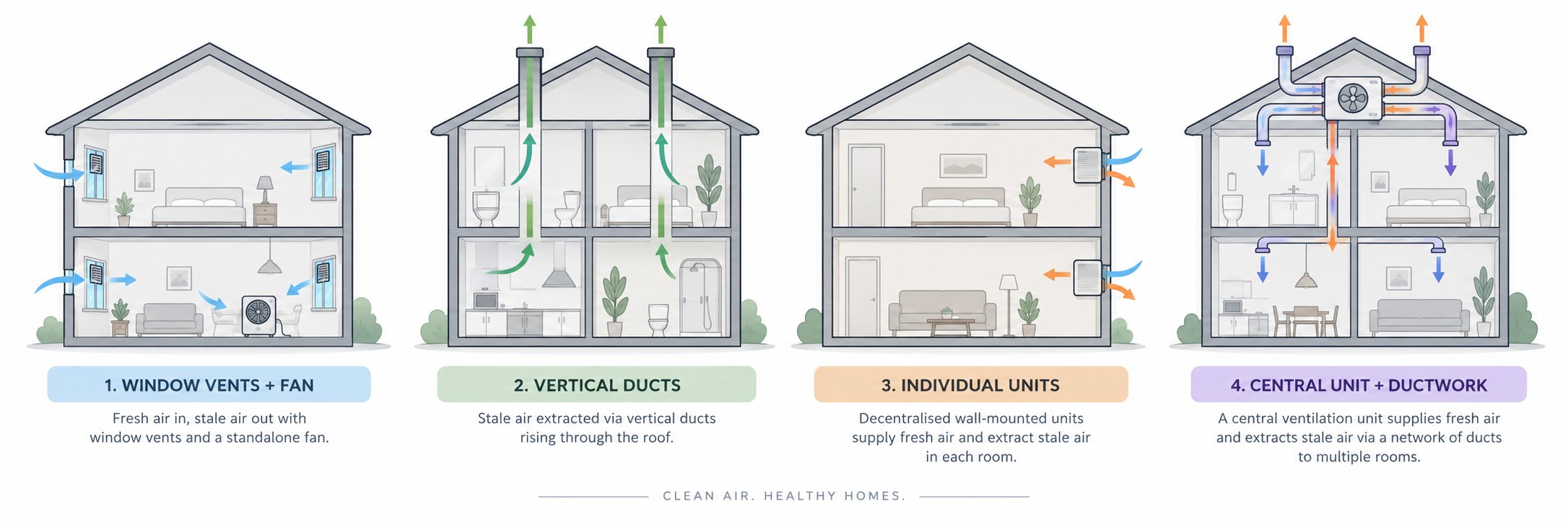
Approved Document F Volume 1 does not leave designers guessing about how to ventilate a dwelling. It defines four distinct ventilation systems, each representing a different balance of cost, complexity, energy performance, and suitability for specific building types. Every compliant residential ventilation strategy in England maps back to one of these four systems. Choosing the wrong one for your project does not just risk poor air quality. It risks failing Building Control inspection entirely.
The table below sets out each system at a glance before the detailed breakdowns that follow.
| System | Type | Key Components | Best Suited For | Pros/Cons |
|---|---|---|---|---|
| System 1 | Natural ventilation with intermittent extract | Trickle vents (background ventilators) in windows/walls plus intermittent extract fans in wet rooms | Naturally ventilated dwellings with moderate airtightness; extensions, renovations, and simple new builds | Pros: Lowest cost, no continuous energy use, simple installation. Cons: No heat recovery, relies on occupant operation of fans, less effective in very airtight buildings |
| System 2 | Passive stack ventilation (PSV) or continuous mechanical extract (MEV) | PSV: Vertical ducts using stack effect. MEV: Central extract fan unit with ducting to wet rooms, plus trickle vents for air supply | PSV suits multi-storey dwellings with vertical duct routes. MEV suits moderately airtight new builds where continuous extraction is preferred | Pros: PSV has no running costs; MEV provides reliable, continuous extraction. Cons: PSV performance is weather-dependent; MEV has no heat recovery and relies on trickle vents for replacement air |
| System 3 | Decentralised mechanical ventilation with heat recovery (dMVHR) | Individual room-based MVHR units installed through external walls, each with its own heat exchanger | Retrofit projects, flats without loft space, single-room applications where full ducting is impractical | Pros: No ductwork network needed, room-by-room installation, heat recovery per unit. Cons: Multiple wall penetrations, variable recovery efficiency, individual units require separate maintenance |
| System 4 | Centralised mechanical ventilation with heat recovery (cMVHR) | Central MVHR unit (typically in loft or utility room), ducted supply to habitable rooms, ducted extract from wet rooms, heat exchanger recovering warmth from outgoing air | Airtight new builds, Passivhaus projects, deep retrofits with air permeability below 5 m³/hr/m² at 50Pa | Pros: Up to 90-95% heat recovery, filtered air supply, best air quality and energy performance. Cons: Highest upfront cost, requires duct network, needs regular filter changes and commissioning |
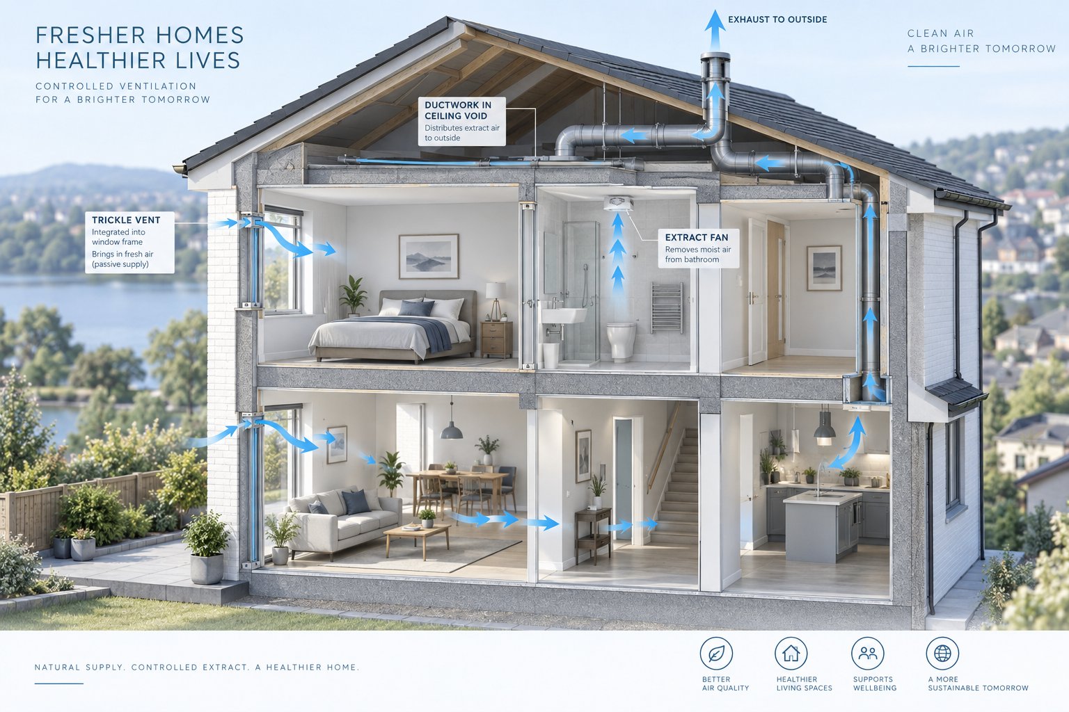
System 1 is the simplest compliant pathway and the one most homeowners and small builders encounter. It combines two elements: background ventilators, typically trickle vents integrated into window frames, that provide a continuous low-level supply of fresh air, paired with intermittent extract fans in "wet rooms" like kitchens, bathrooms, utility rooms, and WCs.
The trickle vents do the quiet, ongoing work. They allow outdoor air to enter habitable rooms without needing any electrical power or occupant intervention beyond opening or closing the vent slot. The extract fans handle the heavy lifting during activities that generate moisture or pollutants, switching on when you cook, shower, or use the bathroom. Minimum extract rates for these fans are prescribed in Approved Document F: typically 30 l/s for a kitchen with an external cooker hood (or 60 l/s without one), 15 l/s for a bathroom, 30 l/s for a utility room, and 6 l/s for a WC.
Why is System 1 so widely used? Cost and simplicity. There is no ductwork network to install, no central plant to accommodate, and no ongoing energy consumption from the background ventilators. For a straightforward extension, a loft conversion, or a naturally ventilated house with moderate airtightness, System 1 often provides the most practical route to compliance.
The limitation? System 1 trickle vents and intermittent extract fans offer no heat recovery whatsoever. Every cubic metre of warm air pulled out by the extract fan is replaced by cold, unfiltered outdoor air entering through the trickle vents. In a draughty older property, this barely matters because the building was already losing heat through gaps and cracks. In a well-insulated, airtight new build, that ventilation heat loss becomes a significant proportion of total energy demand, which is precisely why tighter airtightness standards under Part L push projects away from System 1 toward mechanical alternatives.
System 2 actually encompasses two quite different technologies grouped under a single heading, and the distinction matters.
Passive stack ventilation (PSV) exploits a basic principle of physics: warm air is lighter than cold air and rises naturally. Vertical ducts run from wet rooms at lower levels up through the building and out through the roof. As warm, moisture-laden air inside the duct rises and exits at roof level, it draws fresh replacement air into the dwelling through background ventilators. No fans, no electricity, no moving parts. The system is entirely passive.
Sounds elegant? It is, in theory. In practice, PSV performance depends heavily on the temperature difference between indoors and outdoors (the "stack effect" weakens in mild weather), wind conditions at the roof terminal, and the vertical height of the duct run. A single-storey bungalow generates far less stack effect than a three-storey townhouse. This unpredictability is why PSV is relatively uncommon in modern construction, appearing more often in mid-rise developments where the duct heights are substantial enough for reliable airflow.
Continuous mechanical extract ventilation (MEV) takes a more dependable approach. A central fan unit, typically installed in the loft, connects via small-bore ducting (usually 75 mm or 100 mm diameter) to extract valves in each wet room. Unlike the intermittent fans in System 1, an MEV unit runs continuously at a low trickle rate, providing constant background extraction 24 hours a day. Most units include a boost mode, activated by a manual switch, humidity sensor, or timer, that increases the extraction rate during high-moisture activities.
Fresh air still enters through trickle vents, just as with System 1. The critical difference is reliability. MEV does not depend on occupants remembering to switch a fan on after a shower. It runs continuously, maintaining steady negative pressure that draws stale air out and pulls fresh air in through the background ventilators. Running costs are modest, typically around 10-20 watts of continuous power consumption.
The trade-off echoes System 1: no heat recovery. Extracted warm air is dumped outside, and cold replacement air enters untreated through the trickle vents. For homes with moderate airtightness, say 8-10 m³/hr/m² at 50Pa, MEV is a solid and cost-effective compliance strategy. Below that threshold, the ventilation heat loss it creates starts undermining the energy performance gains that the airtight envelope was designed to deliver.
When a building is sealed tightly enough that ventilation heat loss becomes the dominant energy penalty, the only logical response is to recover that heat before it leaves the building. That is exactly what MVHR systems do, and Approved Document F defines two variants.
System 3: Decentralised MVHR (dMVHR) uses individual, self-contained units installed through external walls in specific rooms. Each unit contains its own small heat exchanger and pair of fans, simultaneously extracting stale air and supplying fresh air through a single wall penetration. The outgoing warm air passes its heat to the incoming cold air through the exchanger, recovering a portion of the energy that would otherwise be lost.
The key advantage of dMVHR is installation flexibility. There is no ductwork network to route through ceilings and floor voids, making it attractive for retrofit projects, flats without loft access, and individual rooms where targeted ventilation is needed. The trade-off is that recovery efficiency in individual wall-mounted units tends to be lower than centralised systems, and each unit requires its own maintenance. You might need several units across a dwelling to achieve whole-house compliance.
System 4: Centralised MVHR (cMVHR) is the most comprehensive ventilation strategy available. A single central unit, typically located in a loft, utility room, or dedicated plant cupboard, connects to two separate duct networks. One network supplies filtered, pre-warmed fresh air to habitable rooms such as bedrooms, living rooms, and studies. The other extracts stale, moisture-laden air from wet rooms. At the heart of the unit, a counter-flow heat exchanger transfers warmth from the outgoing extract air to the incoming supply air without the two air streams ever mixing.
Modern cMVHR units achieve heat recovery efficiencies of 90-95%, meaning that on a cold winter day, outdoor air at 2°C can be pre-warmed to around 18-19°C before it even enters your living space. The incoming air is also filtered, typically to F7 grade, capturing pollen, fine dust, and diesel particulates. Many quality units include a summer bypass that automatically routes cool outdoor air directly into the building when heat recovery is not needed, providing free passive cooling.
Why are Systems 3 and 4 increasingly the default specification for new builds? The answer lies in Part L. As airtightness targets have tightened, with current standards requiring air permeability no greater than 8 m³/hr/m² at 50Pa and many new homes achieving 3-5 m³/hr/m² in practice, the regulatory framework effectively nudges designers toward MVHR. At these airtightness levels, Systems 1 and 2 create unacceptable ventilation heat loss that undermines the building's energy performance calculations. MVHR improves SAP compliance figures by reducing the ventilation heat loss factored into energy demand assessments, often delivering 5-10 additional SAP points compared to extract-only strategies. For developers trying to meet Target Emission Rates without over-specifying heating plant, that margin can be the difference between passing and failing.
The upfront cost reflects the sophistication. A typical centralised MVHR installation in a 3-4 bedroom house runs between £4,000 and £8,000, compared to £1,000-£2,500 for MEV and a few hundred pounds for System 1 components. However, annual heating savings of £200-£500 through heat recovery can close that gap significantly over a 15-year lifecycle, while delivering measurably better indoor air quality throughout.
The system numbers in Approved Document F give designers a shared language for describing ventilation strategies. Yet a system number alone does not guarantee compliance. Each system must deliver specific minimum airflow rates, and those rates, measured in litres per second, are where the real regulatory detail lives.
Here is where most online guides fall short. They tell you minimum ventilation rates exist, point you toward the official documents, and leave you to hunt through dozens of pages. This section eliminates that step entirely. The tables below reproduce the actual figures from Approved Document F Volume 1 (2021 edition), giving you the reference data you need to specify, install, and verify compliant ventilation in any dwelling.
Three sets of figures matter most: extract rates for individual wet rooms, whole-dwelling ventilation rates scaled by bedroom count, and trickle ventilator equivalent area thresholds for background ventilation. Each serves a different compliance function, and getting any one of them wrong is enough to fail a Building Control inspection.
Extract ventilation removes moisture and pollutants at source, directly from the rooms where they are generated. Approved Document F specifies minimum extract rates for two operating modes: intermittent extraction (fans that activate during or after activities like cooking and bathing) and continuous extraction (fans that run constantly with a boosted high rate for peak demand).
The intermittent rates, drawn from ADF Table 1.1, apply to System 1 installations where extract fans operate on demand. The continuous high rates, from ADF Table 1.2, apply to Systems 3 and 4, where centralised or decentralised mechanical extract runs constantly and boosts to a higher rate when a room is occupied or humidity spikes.
| Room Type | Intermittent Extract Rate (l/s) — Table 1.1 | Continuous High Rate (l/s) — Table 1.2 |
|---|---|---|
| Kitchen (with cooker hood extracting to outside) | 30 | 13 |
| Kitchen (no cooker hood, or hood not extracting to outside) | 60 | 13 |
| Utility room | 30 | 8 |
| Bathroom (with bath or shower) | 15 | 8 |
| Sanitary accommodation (WC / cloakroom) | 6 | 6 |
Notice the dramatic difference in the kitchen. A ducted cooker hood extracting directly to the outside halves the required intermittent rate from 60 l/s down to 30 l/s. A recirculating cooker hood, no matter how effective its filters, does not count as extraction under Part F. If your kitchen has only a recirculating hood, you must provide a separate extract fan delivering the full 60 l/s. That figure is demanding. A standard 100 mm (4-inch) axial fan will struggle to achieve it against any meaningful duct resistance, which is why trade guidance recommends a 150 mm (6-inch) fan in kitchens without a ducted hood.
For sanitary accommodation, a small concession applies: purge ventilation via an openable window is accepted as an alternative to a mechanical extract fan. This exception does not extend to bathrooms. Even if your bathroom has a large openable window, a mechanical extract fan delivering at least 15 l/s is still required.
Individual room extract rates handle localised pollutants. Whole-dwelling ventilation rates address a different problem: ensuring enough total air exchange across the entire home to dilute general pollutants like CO2, volatile organic compounds from furnishings, and residual moisture. These rates, specified in ADF Table 1.3, apply to continuous extract systems (MEV and MVHR) and determine the minimum total airflow the system must deliver on its continuous low-speed setting.
| Number of Bedrooms | Minimum Whole-Dwelling Ventilation Rate (l/s) |
|---|---|
| 1 bedroom | 19 |
| 2 bedrooms | 25 |
| 3 bedrooms | 31 |
| 4 bedrooms | 37 |
| 5 bedrooms | 43 |
| Each additional bedroom beyond 5 | Add 6 l/s |
| Dwelling with only one habitable room (e.g., studio flat) | 13 |
The logic behind the scaling is straightforward: more bedrooms means more assumed occupants, and more occupants generate more pollutants and moisture. Each additional bedroom beyond five adds a further 6 l/s to the minimum rate.
Here is the detail that catches many designers out. The whole-dwelling ventilation rate must satisfy two criteria simultaneously, not just the bedroom-count figure from Table 1.3. ADF also requires that the continuous rate is at least 0.3 l/s per m² of total internal floor area (all floors combined). You must calculate both figures and use whichever is higher. For a generously sized 4-bedroom house with 180 m² of internal floor area, the bedroom-count figure gives 37 l/s, while the floor-area calculation gives 54 l/s (180 x 0.3). In that case, 54 l/s becomes the binding requirement, a full 46% higher than the bedroom-count figure alone would suggest.
This dual test prevents undersized ventilation in large dwellings with relatively few bedrooms, such as open-plan barn conversions or homes with expansive living areas. Ignoring it means your MEV or MVHR system may appear compliant on a schedule but will fail a commissioning test when airflow measurements are taken.
Trickle vents provide the continuous background air supply that replaces the stale air being extracted. Their capacity is measured not in litres per second, but in equivalent area (EA), expressed in mm² and tested to BS EN 13141-1. Equivalent area is not the same as the physical opening area of the vent slot. It accounts for the aerodynamic resistance of the ventilator's internal baffles, insect screens, and rain deflectors. Two vents with identical physical slot sizes can have very different equivalent areas depending on their internal design.
Approved Document F Table 1.7 specifies minimum equivalent areas based on room type, dwelling configuration, and ventilation system. The thresholds differ depending on whether the dwelling has one floor or multiple floors, and whether the system uses natural ventilation (System 1) or continuous mechanical extract (System 3).
| Room Type | System 1 — Multi-Storey Dwelling (mm² EA) | System 1 — Single-Storey Dwelling (mm² EA) | System 3 (MEV) — All Dwellings (mm² EA) |
|---|---|---|---|
| Habitable room (bedroom, living room, dining room) | 8,000 | 10,000 | 4,000 |
| Kitchen | 8,000 | 10,000 | Not required |
| Bathroom | 4,000 | 4,000 | Not required |
| Utility room | No minimum specified | No minimum specified | Not required |
| Sanitary accommodation (WC) | No minimum specified | No minimum specified | Not required |
Why do single-storey dwellings need larger equivalent areas? Because they lack the vertical stack effect that helps drive airflow through a multi-storey building. Without the natural buoyancy advantage created by warm air rising through multiple floor levels, a single-storey home needs wider vent openings to achieve the same background air exchange.
When continuous MEV is installed (System 3), the required equivalent areas drop to 4,000 mm² per habitable room and no trickle vents are needed in wet rooms at all. The continuous mechanical extraction creates sufficient negative pressure to draw replacement air through the smaller habitable-room ventilators. For MVHR systems (System 4), background ventilators should not be fitted, since the system provides its own filtered supply air through dedicated ductwork.
A few additional rules from ADF Table 1.7 that are easy to overlook:
That last point trips up installers regularly. Claiming "the old windows didn't have vents" is explicitly not an acceptable compliance route. Replacing windows increases airtightness, reducing the uncontrolled air leakage that the original glazing allowed. The regulation requires that ventilation is not made less satisfactory as a result of the work, and fitting new, tighter windows without background ventilators does exactly that.
These figures form the quantitative backbone of every compliant ventilation design. Yet applying them correctly requires knowing which regulatory framework applies to your project, and that depends entirely on where in the UK the building sits. The same dwelling built in Edinburgh, Cardiff, Belfast, or Bristol faces different regulatory documents, different oversight bodies, and potentially different compliance thresholds.

Here is the detail that virtually every online guide gets wrong, or simply ignores: the term "UK building regulations" does not refer to a single set of rules. The United Kingdom comprises four nations, each with its own regulatory framework, its own guidance documents, and its own enforcement bodies for building standards. A ventilation design that passes Building Control in Manchester may not satisfy the requirements in Glasgow, Cardiff, or Belfast. If your work crosses national boundaries, or if you are simply searching for "uk building regulations ventilation" from outside England, you need to know exactly where the differences lie.
The table below maps the regulatory landscape for all four nations at a glance.
| Nation | Primary Document | Key Differences from England | Regulatory Body |
|---|---|---|---|
| England | Approved Document F, Volumes 1 and 2 (June 2022 edition; 2026 edition published) | Baseline reference. Four defined ventilation systems for dwellings. Prescriptive extract rates and trickle vent equivalent areas. | Local Authority Building Control (LABC) or Approved Inspectors (now Registered Building Control Approvers) |
| Scotland | Building Standards Technical Handbook 2022, Section 3.14 | Performance-based mandatory standard. Higher trickle vent areas (12,000 mm² for habitable rooms). CO2 monitoring required in bedrooms for airtight dwellings. Different extract rates (e.g., 30 l/s kitchen above hob, 60 l/s elsewhere). | Local Authority Building Standards (verified by appointed building standards officers) |
| Wales | Welsh Approved Document F, Volumes 1 and 2 | Closely mirrors England's framework but published as separate Welsh editions. A new Volume 1 for dwellings takes effect on 4 March 2027. Potential local amendments may diverge from the English editions over time. | Local Authority Building Control (LABC) |
| Northern Ireland | Technical Booklet K — Ventilation | Separate document under the Building Regulations (Northern Ireland) 2012. Covers regulations 65, 66, and 68. Published in October 2012 and not updated as frequently as England's framework. Different document structure and numbering. | District Council Building Control |
The previous chapters of this guide have covered the English framework in depth, so a brief recap serves as the benchmark for comparison. England's ventilation requirements sit within Approved Document F, split into Volume 1 for dwellings and Volume 2 for non-domestic buildings. Volume 1 defines four prescriptive ventilation systems, sets minimum extract rates by room type, specifies whole-dwelling ventilation rates by bedroom count, and establishes trickle ventilator equivalent area thresholds. The June 2022 edition brought tighter integration with Part L airtightness standards, new cross-references to Part O overheating provisions, and mandatory trickle vents in replacement windows.
England's framework is the most frequently updated among the four nations, with a 2026 edition of Volume 1 already published. That pace of revision matters. It means that the English requirements often represent the most demanding current standard, and professionals working UK-wide need to track whether the other three nations have adopted equivalent updates or retained earlier thresholds.
Scotland – A performance-based approach with unique provisions
Scotland operates under an entirely separate legislative framework: the Building (Scotland) Regulations 2004, administered by the Scottish Government rather than the UK Government in Westminster. Ventilation requirements appear in Section 3.14 of the Building Standards Technical Handbook 2022 (Domestic), and the mandatory standard reads differently from England's Part F. It states that every building must be designed and constructed so that ventilation is provided ensuring the air quality inside the building is not a threat to the building or the health of the occupants.
That phrasing is broader and more performance-oriented than England's functional requirement, and the practical guidance diverges in several material ways:
The Scottish system also references different industry guidance documents, including BRE Information Paper IP 13/94 for passive stack ventilation and CIBSE Guide B2 for mechanical ventilation, rather than relying solely on the structure of England's four numbered systems.
Wales – Closely aligned with England, but separately published
Wales publishes its own editions of Approved Document F under the Building Regulations 2010 (as amended for Wales). The Welsh Government's Approved Document F page hosts both Volume 1 (dwellings) and Volume 2 (non-domestic buildings). The current editions mirror the English framework closely in structure and technical content, using the same four ventilation system types, the same extract rate tables, and the same equivalent area thresholds.
Where should you watch for divergence? Wales has already published a new Volume 1 for dwellings that takes effect on 4 March 2027, signaling that the Welsh Government intends to continue evolving its building standards independently. Over time, Welsh-specific amendments may introduce requirements that depart from the English editions, particularly around energy efficiency and overheating, where Wales has shown willingness to set its own pace. For projects in Wales, always verify you are using the Welsh edition of the Approved Document, downloaded from gov.wales, not the English version from gov.uk.
Northern Ireland – Technical Booklet K
Northern Ireland sits under its own legislative framework entirely: the Building Regulations (Northern Ireland) 2012, administered by the Department of Finance. Ventilation guidance is provided in Technical Booklet K, which covers requirements under regulations 65, 66, and 68. Published in October 2012, Technical Booklet K has not undergone the same cycle of revisions that England's Approved Document F has experienced. This means that while the fundamental principles — extract ventilation in wet rooms, background ventilation via trickle vents, mechanical systems for airtight envelopes — remain consistent, the specific numerical thresholds and system classifications in Northern Ireland may not reflect the more recent uplift in extract rates and equivalent area requirements seen in England's 2022 edition.
For professionals accustomed to the English framework, the biggest adjustment is navigational. Technical Booklet K uses different regulation numbers, different document structure, and different terminology in places. District Council Building Control in Northern Ireland is the enforcement body, rather than the LABC or Registered Building Control Approvers used in England.
Imagine you are an architect designing a housing portfolio for a developer with sites in Birmingham, Edinburgh, Swansea, and Belfast. You cannot write a single ventilation specification and assume it applies everywhere. Each site falls under a different regulatory document, verified by a different enforcement body, against potentially different numerical standards.
Here is how to navigate that complexity without creating four entirely separate design processes:
The four-nation picture reveals something important about how ventilation regulations function in practice: they do not exist in a vacuum. Each nation's ventilation framework connects to its own parallel requirements for airtightness, energy efficiency, fire safety, and overheating. Those interconnections — the tensions and trade-offs between different regulatory objectives within a single nation's framework — shape every design decision on site, and they deserve their own detailed examination.
Designing a ventilation system to satisfy Part F alone is the easy part. The real challenge emerges when you realise that three other Approved Documents — Part L (conservation of fuel and power), Part O (overheating), and Part B (fire safety) — each impose their own demands on the same building envelope, the same ductwork, and the same window openings. These documents were written separately, but they must be satisfied simultaneously. The result is a web of interconnected requirements that frequently pull in opposite directions, forcing designers to resolve tensions that no single document acknowledges on its own.
Imagine building a house so well-sealed that almost no air leaks through the walls, floors, or roof. Part L rewards that ambition. Tighter envelopes mean less uncontrolled heat loss, lower energy bills, and better SAP ratings. Current minimum air permeability standards under Approved Document L Volume 1 require no more than 8.0 m³/(h·m²) at 50 Pascals, but most new dwellings achieve significantly better figures to meet the broader energy performance targets for primary energy rate, emission rate, and fabric energy efficiency.
Here is the paradox: the tighter you build, the less natural background air infiltration occurs — and the more dependent you become on deliberately engineered ventilation under Part F. A leaky older home with air permeability around 12-15 m³/(h·m²) gets a substantial portion of its fresh air supply through uncontrolled gaps around windows, service penetrations, and floor junctions. That air exchange is uncontrolled, energy-wasteful, and draughty, but it does dilute pollutants and carry away moisture. Seal those gaps, and every molecule of fresh air must arrive through a designed ventilation pathway.
The regulatory consequence is direct. Approved Document F Volume 1 explicitly states that natural ventilation (System 1) is not suitable for highly airtight dwellings. A dwelling is classified as highly airtight when it has either a design air permeability below 5 m³/(h·m²) at 50Pa or an as-built air permeability below 3 m³/(h·m²) at 50Pa. Cross either threshold, and your ventilation strategy is restricted to continuous mechanical extract (MEV) or mechanical ventilation with heat recovery (MVHR) — Systems 2, 3, or 4.
This creates a scenario that catches builders more often than you might expect. A developer designs a housing scheme with System 1 ventilation — trickle vents and intermittent extract fans — assuming moderate airtightness. Construction quality turns out better than anticipated, and the mandatory pressure test reveals an as-built air permeability of 2.5 m³/(h·m²) at 50Pa. The dwelling is now classified as highly airtight, and System 1 is no longer compliant. As LABC guidance explains, the developer then faces two options: commission an expert assessment demonstrating that Part F compliance is still achieved, or retrofit a continuous mechanical extract system. Neither option is cheap or simple at that stage of a build, which is why experienced designers account for how Part L airtightness affects ventilation strategy from day one rather than treating them as separate compliance exercises.
Part O, introduced in June 2022, added another layer of complexity. Its purpose is to mitigate overheating risk in new residential buildings — a growing concern as summers get warmer and buildings get more insulated. The primary compliance tool? Ventilation. Specifically, openable windows large enough to provide purge ventilation and cross-ventilation that flush excess heat out of the dwelling.
Sounds like a natural partner for Part F. In practice, the Part O overheating purge ventilation requirements frequently collide with other regulatory objectives. Harwood Building Control highlights several of the sharpest conflicts:
Commissioning alignment adds yet another friction point. Designers sometimes specify ventilation rates for Part F compliance in litres per second, while TM59 reports express rates in air changes per hour. If commissioning records do not reconcile both formats, Building Control may reject the submission even when the installed system performs adequately. The lesson? Part F and Part O compliance must be coordinated from the design stage, with commissioning documentation explicitly addressing both documents' requirements in the correct units.
Approved Document B governs fire safety, and its implications for ventilation design are substantial. Every duct that passes through a fire-rated wall, floor, or ceiling penetrates a fire compartment boundary — a boundary that exists to contain fire and smoke within a defined area and protect escape routes. If ventilation ductwork breaches that boundary without adequate protection, it becomes a conduit for fire and smoke to spread through the building.
Part B requires fire dampers at specific locations within ductwork to prevent exactly this. Fire dampers are mechanical devices installed where ducts pass through fire-rated construction. They remain open during normal operation, allowing unrestricted airflow, but close automatically when triggered by heat — typically via a fusible link that melts at a defined temperature — sealing the duct and maintaining the compartment's fire resistance rating. The fire resistance of the damper must match the rating of the wall or floor it penetrates.
The fire damper ventilation ductwork Part B regulations also impose requirements on materials, routing, and ongoing maintenance:
The interaction between Parts B and F is particularly acute in the exact building types where MVHR is most needed: airtight, multi-storey residential developments. These are the projects where Part L pushes airtightness low enough to mandate mechanical ventilation, Part O may require large openable windows that conflict with security and guarding rules, and Part B demands fire-rated ductwork and dampers that constrain the routing of the mechanical system being mandated by the other three documents. Resolving these competing requirements is not a theoretical exercise — it is the daily reality of compliant building design.
Understanding these regulatory interactions matters most at the component level, where individual products like trickle ventilators must satisfy Part F airflow requirements while also addressing acoustic performance, frame compatibility, and installation practicality in both new and existing buildings.
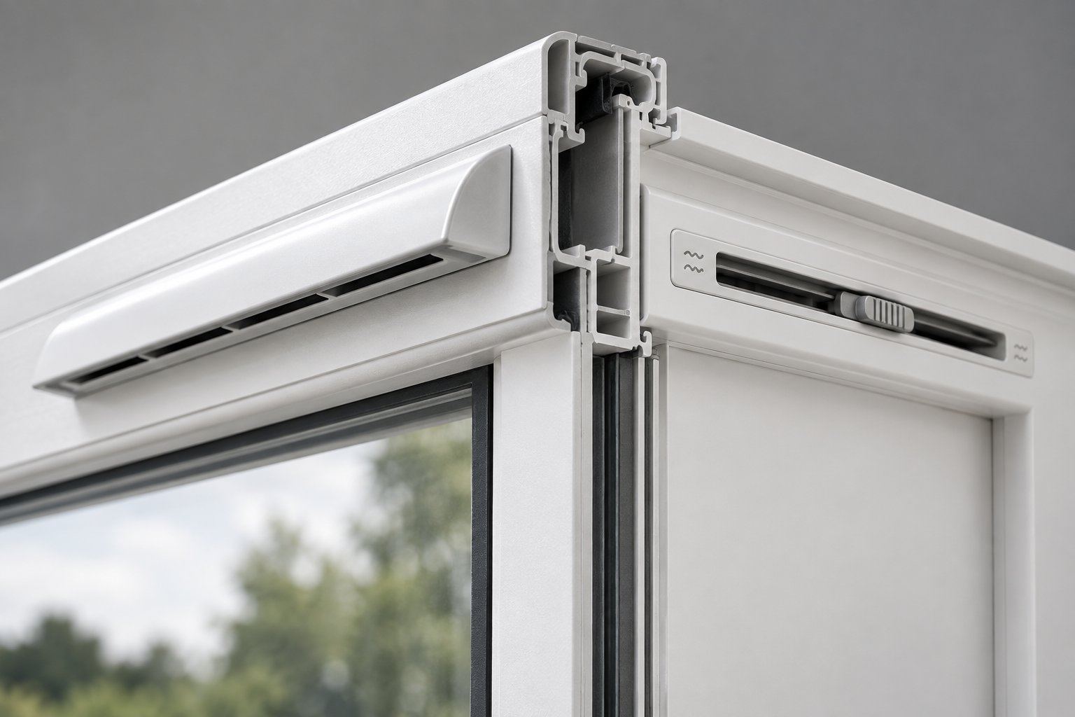
Regulatory frameworks, cross-document tensions, minimum airflow tables — all of that technical infrastructure ultimately funnels down to a deceptively simple component sitting at the top of your window frame. Trickle ventilators are the most commonly installed ventilation product in UK dwellings, and for most renovation and replacement window projects, they represent the single most important compliance decision you will make under Part F.
A trickle vent is a small, slotted opening integrated into the window frame head (or sometimes the transom) that allows a controlled trickle of outdoor air to enter the room even when the window is fully closed and locked. It requires no electrical power, no ductwork, and no occupant intervention beyond the option to slide the internal cover open or closed. Paired with intermittent extract fans in wet rooms, trickle vents form the backbone of System 1 ventilation — the simplest and most affordable compliance pathway for naturally ventilated homes.
Yet "simple" does not mean "optional." Since 15 June 2022, trickle vents are mandatory in replacement windows under building regulations, and the consequences of omitting them extend far beyond a failed inspection. Understanding what the regulations require, what specifications a vent must meet, and how to select a product that satisfies Part F without compromising acoustic comfort or frame aesthetics is essential for every architect, specifier, fabricator, and installer working in the fenestration sector.
Before the June 2022 update to Approved Document F, the rules around trickle vents in replacement windows were narrower. If the existing windows already had trickle vents, the replacements had to include them. If the old windows had none, installers could often avoid fitting vents in the new frames. That loophole is now closed.
The updated regulations recognise a straightforward physical reality: replacing old, draughty single- or double-glazed windows with modern high-performance units dramatically increases the airtightness of the building envelope. Those original windows, with their imperfect seals and worn gaskets, were allowing uncontrolled background air infiltration. Remove that infiltration without compensating for it, and you have reduced the dwelling's ventilation capacity — potentially below the threshold required for healthy indoor air quality. Moisture accumulates, condensation forms on cold surfaces, and mould growth follows.
The current edition of Approved Document F Volume 1 addresses this directly. For replacement windows in existing dwellings, the regulation stipulates that background ventilators must be provided regardless of whether the original windows included them. As FENSA-registered installers confirm, any replacement window installed after this date must meet the updated ventilation requirements, or the installation will fail its inspection and will not be eligible for a building control compliance certificate.
The practical consequences of non-compliance are significant. An installation registered as non-compliant remains on file with the local authority. If the homeowner later tries to sell the property, conveyancing solicitors will identify the absence of a valid compliance certificate and may block the transaction until remediation is completed. Retrofitting trickle vents into already-installed windows is substantially more expensive and disruptive than specifying them correctly from the start — requiring on-site routing of the frame, potential scaffold erection for upper-floor access, and risk of cosmetic damage to the finished product.
A common misconception deserves correction here. Night vents — the locking position that holds a window slightly ajar — do not satisfy the background ventilation requirement. As industry fabrication guidance explicitly states, night vents do not provide the secure, consistent, and controllable background airflow required by the regulations. They leave windows physically open, compromising security and weather resistance, and their airflow performance is neither tested nor measurable against equivalent area standards.
Selecting the right trickle vent is not simply a matter of choosing one from a catalogue and screwing it to the frame. Three technical dimensions determine whether a vent achieves Part F compliance: equivalent area rating, acoustic attenuation, and physical compatibility with the window frame profile.
Equivalent area (EA) is the critical performance metric. It measures the effective airflow capacity of the vent, expressed in mm², and is tested to BS EN 13141-1. Crucially, equivalent area is not the physical size of the slot opening. It represents the area of a sharp-edged circular orifice through which air would pass at the same volume flow rate, under identical pressure, as through the vent itself. Internal baffles, insect meshes, rain deflectors, and the geometry of the airflow path all reduce the equivalent area relative to the raw slot dimensions.
The minimum equivalent area thresholds from Approved Document F Table 1.7, detailed earlier in this guide, set the compliance bar:
| Location | Multi-Storey Dwelling (mm² EA) | Single-Storey Dwelling (mm² EA) |
|---|---|---|
| Habitable rooms and kitchens | 8,000 | 10,000 |
| Bathrooms or rooms with an extract fan | 4,000 | 4,000 |
In practical terms, a single trickle vent typically provides around 4,000 mm² EA. To reach the 8,000 mm² threshold for a habitable room in a multi-storey dwelling, you will generally need two vents per window — or a single high-capacity unit. For a bungalow or ground-floor flat, where the 10,000 mm² threshold applies, three standard 4,000 EA vents or a combination of higher-rated units may be necessary. Over-specifying is always safer than under-specifying; as fabrication specialists note, failure to hit the target equivalent area means the installation will not meet building regulations, full stop.
Where the equivalent area target genuinely cannot be achieved — for example, in a very narrow window where there is physically insufficient frame head length to accommodate the required vents — Approved Document F permits the ventilation to be "as close to the minimum value as is feasible." This is a limited concession, not an invitation to routinely under-specify. Building Control will expect documented evidence that the constraint is genuine and that all reasonable steps were taken to maximise the achievable equivalent area.
Acoustic performance becomes a critical consideration for properties near roads, railways, or flight paths. Standard trickle vents, while effective at delivering background airflow, offer little resistance to external noise transmission. The open slot that allows air to enter also allows sound to pass through largely unimpeded. For noise-sensitive sites, acoustic trickle vents incorporate internal baffles, absorption chambers, and denser materials that attenuate sound energy while maintaining the required equivalent area.
Approved Document F itself flags this requirement: where an exposed facade is close to an area of sustained and loud noise, a noise-attenuating background ventilator should be fitted. Specifiers should look for vents tested and rated to a declared sound reduction level, typically expressed as Dn,e,w or similar weighted values. An acoustic vent that delivers 4,000 mm² EA with 33-42 dB of element-normalised sound attenuation can transform the livability of a bedroom overlooking a busy trunk road — a compliance win that also delivers measurable occupant satisfaction.
Frame integration is the third dimension, and it matters more than many specifiers appreciate. Trickle vents must physically fit the window frame profile without compromising structural integrity, weather resistance, or aesthetics. This requires precise routing — a machined channel cut into the frame head to accommodate the external canopy and internal ventilator. Incorrect routing is a common cause of whistling vents, restricted airflow, and components working loose over time.
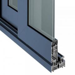
Most trickle vent systems consist of two parts: an external canopy or flush grille that shields against rain and insects, and an internal controllable ventilator that allows the occupant to open or close the airflow. Both components must align precisely with the routed channel. For uPVC windows, the routing is typically performed during fabrication using CNC-controlled machinery. For aluminium windows, frame extension profiles or dedicated vent housings are often specified to accommodate the ventilator without cutting into primary structural members.
Products like Shengxin Aluminium's Window Trickle Vents, designed as a uPVC passive ventilation system, illustrate how compliance-led engineering addresses all three dimensions simultaneously. These vents are manufactured for direct integration into both aluminium and uPVC frame profiles, with tested equivalent area ratings for Part F compliance and noise-conscious design suited to residential facades exposed to external noise sources. For fabricators and window manufacturers sourcing components that satisfy regulatory requirements without requiring bespoke frame modifications, frame-ready trickle vent systems like these reduce both production complexity and installation risk.
To summarise, any trickle vent specified for a Part F-compliant installation must satisfy a clear set of criteria:
Getting these details right at the specification stage prevents the cascading problems that emerge downstream — failed inspections, costly retrofitting, and compliance certificates that cannot be issued. Yet even a perfectly specified trickle vent can become a compliance failure if the broader installation does not satisfy Building Control's verification process. Understanding exactly what inspectors look for, and where installations most commonly fall short, is what separates a smooth sign-off from an enforcement notice.
A ventilation system can be perfectly designed on paper and still fail on site. The gap between specification and installation is where most compliance problems live, and Building Control Bodies exist specifically to close that gap. Whether your project is inspected by a local authority building control (LABC) team or a registered building control approver (RBCA), the verification process follows a structured checklist — and ventilation is one of the areas inspectors scrutinise most closely, precisely because it is one of the areas most frequently done wrong.
Understanding what inspectors look for, which documentation they expect, and what triggers enforcement action gives you the ability to resolve issues before they escalate into costly delays, formal notices, or worse.
A building control ventilation inspection checklist is not a single visit. Inspectors typically review ventilation at multiple stages: during the plan-check phase (verifying the proposed strategy against Part F), during construction (checking ductwork routing, fan locations, and trickle vent installation), and at final inspection before issuing a completion certificate. Here is what they are looking for at each stage:
| Inspection Stage | What the Inspector Checks | Evidence Required |
|---|---|---|
| Plan check / initial notice | Ventilation strategy matches the selected system (1-4). Extract rates and whole-dwelling rates meet ADF Table 1.1, 1.2, and 1.3 minimums. Trickle vent equivalent areas meet Table 1.7. Ductwork routing respects fire compartmentation under Part B. | Ventilation design drawings, specification schedules, product data sheets with tested EA and airflow performance. |
| During construction | Trickle vents installed in correct positions (at or above 1,700 mm AFL, minimum 500 mm from extract fans). Ductwork installed without excessive bends, kinks, or length that would reduce airflow. Fire dampers fitted where ducts penetrate fire compartment boundaries. Extract fans wired and functional. | On-site visual inspection. Installer may need to demonstrate duct runs before they are concealed behind finishes. |
| Pre-completion / final | Commissioned airflow rates measured at each terminal against design specification. Trickle vents open and operational. Extract fans achieving minimum l/s rates. MVHR balanced and filters accessible. Commissioning sheet completed and signed. | Completed domestic ventilation commissioning sheet (Appendix C of ADF Volume 1). Operating and maintenance instructions provided to the building owner. |
The commissioning sheet deserves particular attention because it is the single document that most frequently holds up a completion certificate. Approved Document F Volume 1 includes a standard commissioning sheet as Appendix C — reproduced by BEAMA as a downloadable template — that must be completed as evidence the system has been correctly installed, inspected, and commissioned. The completed sheet must be submitted to the building control body within 5 days for new dwellings, or within 30 days in all other cases. A copy must also be given to the building owner alongside operating and maintenance instructions for the ventilation system.
Without that signed ventilation commissioning certificate, Building Control cannot confirm that the installed system delivers the airflow rates specified at design stage. No commissioning evidence means no completion certificate — regardless of how good the installation looks visually.
Certain problems appear on inspection reports with frustrating regularity. Most are entirely preventable with basic attention to the specification and installation details covered in earlier chapters of this guide. Here are the most frequent failure points:
Every item on this list represents real cost: the cost of return visits, remedial work, delayed handovers, and frustrated clients. A ten-minute pre-inspection self-audit against these points catches the majority of issues before the inspector arrives.
What actually happens when ventilation work fails to comply? The consequences escalate from informal correction through to criminal prosecution, depending on the severity and the response of the responsible parties.
The Planning Portal sets out the enforcement framework clearly. Under section 2A of the Building Regulations 2010, the client, designer, and contractor all have a legal duty to comply with the relevant requirements. Contravening building regulations is a criminal offence that may lead to an unlimited fine and imprisonment.
In practice, enforcement follows a graduated pathway:
Where a registered building control approver (RBCA) is providing the building control service rather than the local authority, the dynamic shifts slightly. RBCAs do not have formal enforcement powers. If they identify non-compliant work and the responsible parties refuse to rectify it, the RBCA will cancel the initial notice, returning the project to the local authority — which then gains full enforcement powers over the work.
Beyond enforcement, the consequences of non-compliance building regulations ventilation failures ripple into property transactions. If Building Control considers that work does not comply and the deficiency is not rectified, no completion or final certificate will be issued. That absence surfaces during a local land search when the property is sold. Conveyancing solicitors will flag the missing certificate, mortgage lenders may refuse to lend against the property, and the transaction stalls until remediation is completed and a regularisation certificate is obtained. Regularisation is not free — it requires a retrospective application to the local authority, potentially including opening up completed work for physical inspection, and paying a fee that is often higher than the original building control charge.
The enforcement framework is designed to be proportionate: most issues resolve informally, and prosecution remains rare for ventilation deficiencies alone. But the financial and practical cost of even a minor compliance failure — a return site visit, a delayed completion certificate, a stalled property sale — is always greater than the cost of getting it right the first time. That calculation applies equally whether you are building a new home from scratch or replacing a single window in an existing dwelling, and it underscores why the choice of ventilation strategy must be informed by the type of project, the building's airtightness, and the full compliance lifecycle from design through to handover.

Every compliance failure explored in the previous section traces back to a single upstream cause: the wrong ventilation strategy was selected for the project, or the right strategy was selected but not through to commissioning. The choice between Systems 1 through 4 is not a matter of preference. It is determined by a matrix of project-specific factors — building type, airtightness target, site constraints, budget, and crucially, whether the work involves a new dwelling or modifications to an existing one. Getting that initial decision right eliminates most of the downstream problems that derail inspections and delay sign-off.
Here is the distinction that catches out more builders and designers than any other: Part F requirements for existing buildings are not the same as those for new construction. Approved Document F Volume 1 draws a clear line between the two, and applying the wrong set of standards to your project is a fast route to either over-engineering (wasting money on unnecessary mechanical systems) or under-specifying (failing inspection because you assumed renovation rules were as lenient as they once were).
New dwellings must comply with the full suite of Part F requirements from the outset. That means selecting one of the four defined ventilation systems, meeting the minimum extract rates from ADF Tables 1.1 and 1.2, achieving whole-dwelling ventilation rates from Table 1.3 (including the often-overlooked 0.3 l/s per m² floor area check), and installing trickle ventilators with equivalent areas matching Table 1.7. Where the dwelling's design air permeability falls below 5 m³/(h·m²) at 50Pa, or as-built testing reveals permeability below 3 m³/(h·m²), natural ventilation via System 1 is ruled out entirely. The project must use continuous mechanical extract or MVHR — Systems 2, 3, or 4.
For anyone choosing a ventilation system for an airtight new build in the UK, the decision often comes down to a straightforward calculation. SAP analysis data shows that MVHR systems reduce space heating demand by 12% at moderate airtightness (5 m³/h/m²) and by 34% at the tightest envelopes (1 m³/h/m²), compared to dMEV. That energy saving directly improves SAP EPC ratings by 4-6%, which for many developers is the margin needed to pass energy performance targets without over-specifying the heating system.
Work on existing buildings operates under different, though not necessarily softer, rules. Approved Document F distinguishes several categories:
The "no worse than existing" principle sounds forgiving, but it has teeth. If a renovation project replaces all windows, adds external wall insulation, and seals service penetrations, the cumulative effect is a substantially tighter building envelope. The ventilation strategy must account for that aggregate tightening, not just each individual element in isolation. Building Control will assess the overall ventilation provision against the building's changed characteristics, and a scheme that was adequate before the work began may no longer pass after it.
Compliance is not a single moment. It is a chain of sequential steps, each dependent on the one before it, running from the earliest design conversations through to post-occupancy maintenance. Break any link, and the entire chain fails. The following lifecycle captures every stage where a ventilation compliance decision must be made or verified:
Every project, whether a 200-unit new build estate or a single replacement window in a Victorian terrace, passes through some version of this lifecycle. The scale changes. The regulatory thresholds change. The sequence does not.
With the regulatory framework, compliance data, cross-document interactions, enforcement consequences, and lifecycle steps all mapped, what does practical decision-making actually look like on a live project? Here are the recommendations that emerge from the full picture:
For airtight new builds (design air permeability below 5 m³/(h·m²) at 50Pa): System 4 centralised MVHR is almost always the right answer. The upfront cost is higher, but the energy savings, SAP compliance benefits, and measurably superior indoor air quality justify the investment. Specify a unit with at least 90% heat recovery efficiency, F7-grade supply filtration, and a summer bypass for passive cooling. Allow adequate space for the unit and ductwork during spatial planning — retrofitting duct routes into a finished building is exponentially more expensive and disruptive than designing them in from the start.
For moderately airtight new builds (5-8 m³/(h·m²) at 50Pa): System 2 continuous mechanical extract (MEV) paired with trickle vents offers a good balance of cost and performance. Continuous extraction eliminates reliance on occupant behaviour, and running costs are modest. The key risk is an as-built pressure test returning a lower-than-expected air permeability, which could push the dwelling into the "highly airtight" classification and disqualify System 2. Discuss contingency strategies with your energy assessor before finalising the specification.
For renovation projects, replacement windows, and change-of-use conversions: System 1 — trickle vents with intermittent extract fans — is typically the simplest and most cost-effective compliance pathway. No central plant, no ductwork network, no ongoing energy consumption from background ventilators. The compliance burden falls squarely on two things: selecting trickle vents with sufficient equivalent area ratings and specifying extract fans capable of delivering the required l/s against realistic duct runs.
This is where product selection becomes genuinely consequential. A trickle vent that falls short of the required equivalent area, does not integrate cleanly with the window frame profile, or fails to attenuate noise on an exposed facade can single-handedly derail an otherwise straightforward compliance exercise. For renovation and replacement window projects where System 1 is the appropriate route, Shengxin Aluminium's Window Trickle Vents offer a practical solution — engineered for Part F compliance with tested airflow performance, noise-conscious design for acoustically sensitive sites, and frame-ready integration for both aluminium and uPVC window profiles. For fabricators and installers who need a trickle vent that satisfies the regulatory equivalent area thresholds without requiring bespoke frame modifications, products designed specifically for this compliance context reduce both procurement risk and on-site installation time.
For all project types, one principle applies universally: treat ventilation as a first-order design decision, not an afterthought. The earlier in the project lifecycle that ventilation strategy is confirmed, the fewer conflicts emerge with airtightness targets, fire compartmentation, overheating mitigation, and spatial planning. The later it is addressed, the more expensive and disruptive every correction becomes — and as the enforcement framework makes clear, the consequences of getting it wrong extend well beyond the construction phase and into the life of the building itself.
Yes. Since 15 June 2022, Approved Document F Volume 1 requires trickle ventilators in all replacement windows, regardless of whether the original windows had them. Replacing old, draughty windows with modern sealed units increases airtightness and reduces background air infiltration. Without compensatory ventilation, indoor moisture and pollutants accumulate, leading to condensation and mould. Installers must fit vents meeting minimum equivalent area thresholds — 8,000 mm² EA for habitable rooms in multi-storey dwellings, 10,000 mm² in single-storey dwellings, and 4,000 mm² in bathrooms. Night vents or windows left ajar do not satisfy this requirement. Non-compliant installations will fail building control inspection, and the absence of a valid compliance certificate can block future property sales. Products such as Shengxin Aluminium's Window Trickle Vents are engineered specifically for Part F compliance with tested equivalent area ratings and frame-ready integration for uPVC and aluminium profiles.
Approved Document F Volume 1 defines four compliant ventilation systems for dwellings. System 1 uses background ventilators (trickle vents) for continuous fresh air supply combined with intermittent extract fans in wet rooms — the simplest and lowest-cost option. System 2 covers either passive stack ventilation (PSV), which uses vertical ducts and natural buoyancy to extract air, or continuous mechanical extract ventilation (MEV), which runs a central fan continuously at low speed. System 3 is decentralised mechanical ventilation with heat recovery (dMVHR), using individual wall-mounted units with built-in heat exchangers — ideal for retrofits without ductwork space. System 4 is centralised MVHR (cMVHR), a whole-house ducted system with a single heat recovery unit achieving up to 95% efficiency. The choice between them depends on building airtightness, project type, budget, and site constraints rather than personal preference.
Part L demands increasingly airtight building envelopes to reduce heat loss, but airtighter buildings need more controlled ventilation to maintain healthy indoor air quality. Approved Document F classifies a dwelling as highly airtight when its design air permeability falls below 5 m³/(h·m²) at 50Pa, or as-built testing reveals below 3 m³/(h·m²) at 50Pa. At these levels, natural ventilation via System 1 (trickle vents with intermittent extract fans) is explicitly ruled out. The dwelling must use continuous mechanical extract (MEV) or mechanical ventilation with heat recovery (MVHR) — Systems 2, 3, or 4. MVHR is particularly favoured in very airtight new builds because it recovers up to 95% of heat from outgoing stale air, offsetting the ventilation heat loss that would otherwise undermine the energy savings achieved by the tight envelope.
Yes, and this is one of the most commonly overlooked aspects of UK ventilation compliance. England uses Approved Document F (Volumes 1 and 2). Scotland operates under Section 3.14 of the Building Standards Technical Handbook 2022, which imposes materially different requirements including higher trickle vent equivalent areas (12,000 mm² for habitable rooms versus England's 8,000 mm²) and mandatory CO2 monitoring in bedrooms of airtight dwellings. Wales publishes its own edition of Approved Document F that closely mirrors England but is evolving independently, with a new Volume 1 effective from March 2027. Northern Ireland uses Technical Booklet K under separate legislation. Professionals working across multiple UK nations should design to the most demanding standard first and verify which specific edition and regulatory body applies to each project site.
Consequences range from informal remediation requests to criminal prosecution. Initially, the local authority will advise the responsible party of the deficiency and allow time for correction — most ventilation failures resolve at this stage. If issues persist, a formal compliance notice can be issued within 12 months, specifying required remedial steps. For serious breaches, a stop notice can halt all site work. Under Section 36 of the Building Act 1984, authorities can require removal or alteration of non-compliant work up to 10 years after completion. Prosecution carries no time limit and can result in unlimited fines. Beyond enforcement, a missing completion certificate surfaces during property sales, potentially blocking mortgage approvals and transactions until a retrospective regularisation certificate is obtained at additional cost.



 Servicio en línea
 0086 136 3563 2360
 sales@sxalu.com
 +86 136 3563 2360
 español
 English
 français
 Deutsch
 русский
 português
 العربية
 ไทย
ไทย Việt
Việt Українська