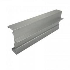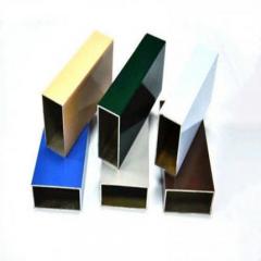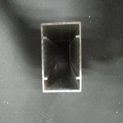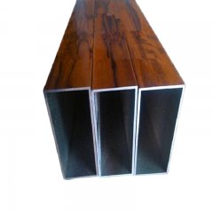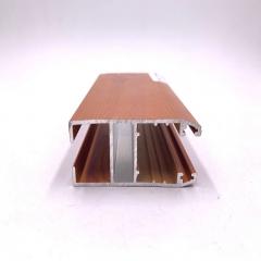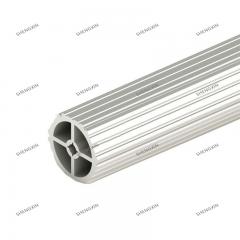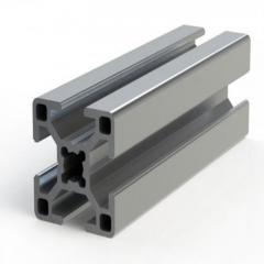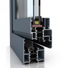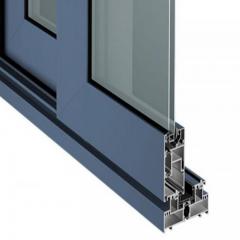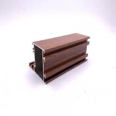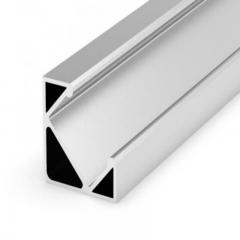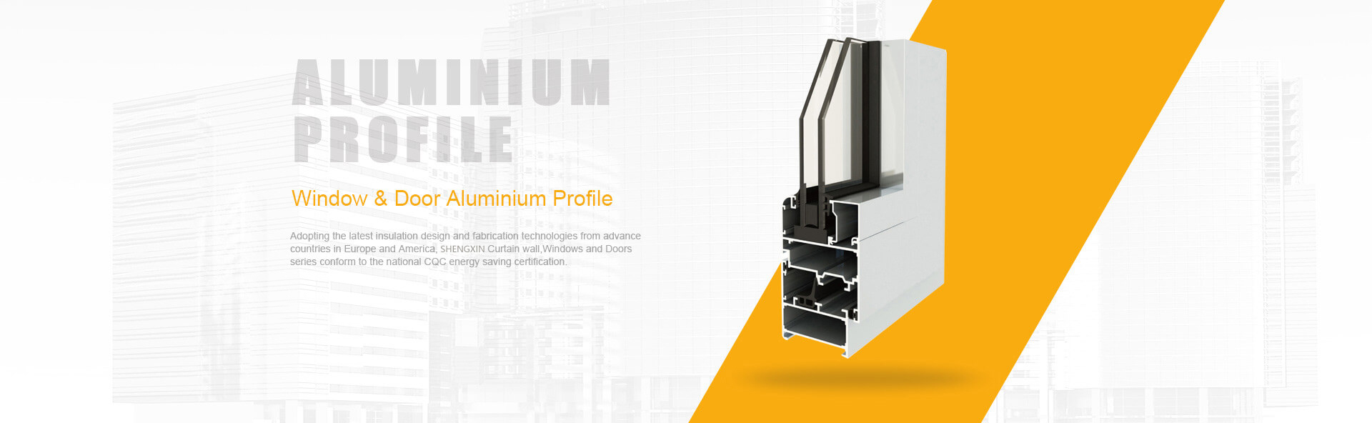
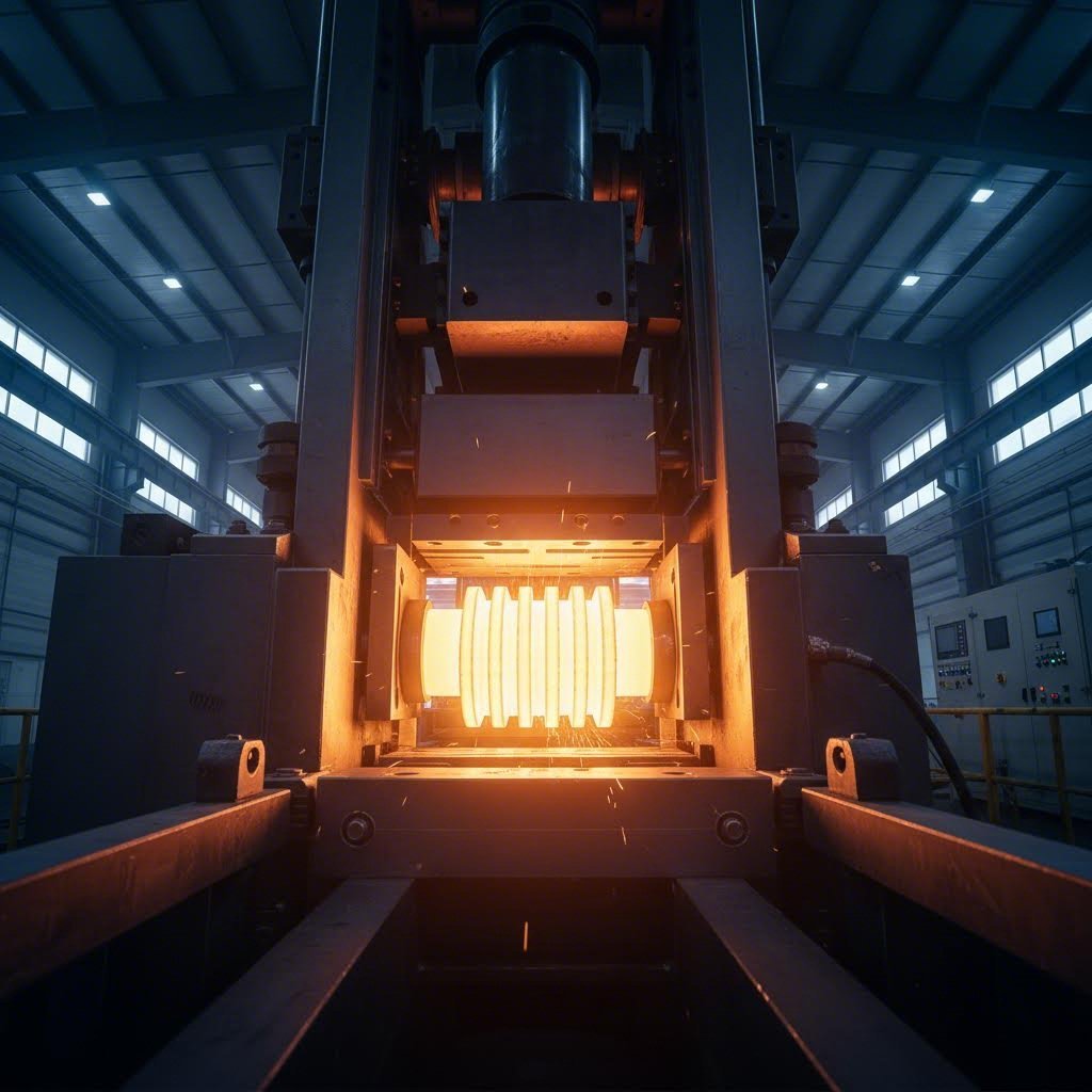
Imagine pushing soft dough through a shaped cookie cutter—that's essentially what happens during the aluminum extrusion process, just at industrial scale with molten metal. To define aluminum extrusion simply, it's a manufacturing technique where a heated aluminum billet gets forced through a specially designed die opening, creating profiles with consistent cross-sections that can stretch to remarkable lengths. This aluminium extrusion definition might sound straightforward, but the devil lies in the design details that determine whether your project succeeds or fails.
Here's the reality that catches many engineers and product designers off guard: the decisions you make on paper today will haunt—or help—your production line for years to come. Poor aluminum extrusion design choices don't just create minor inconveniences. They trigger expensive die revisions, cause production delays that ripple through supply chains, and sometimes compromise the structural integrity of finished products entirely.
Unlike machining, casting, or fabrication, extrusion creates complex cross-sectional shapes in a single pass. You can integrate multiple functions—structural support, thermal management, mounting features—into one seamless profile. This capability makes proper upfront design absolutely critical. When you define extruded aluminum components correctly from the start, you unlock manufacturing efficiencies that other processes simply cannot match.
The process itself is elegantly simple in concept: a cylindrical aluminum billet gets heated to roughly 800-925°F, then hydraulic pressure forces this softened metal through a steel die. What emerges is a continuous length of precisely shaped material, ready for cutting, finishing, and assembly.
The aluminum extrusion definition extends beyond the physical process—it encompasses the entire design-to-production workflow where early choices create lasting consequences.
Industry research consistently shows that approximately 80% of manufacturing costs become locked in during the design phase, long before the first billet ever meets the extrusion press.
This statistic should reshape how you approach every project. Once a die is manufactured and production begins, changing course becomes exponentially more expensive. Wall thickness adjustments require new tooling. Tolerance modifications may demand entirely different process parameters. What seemed like minor design oversights transform into major budget overruns.
This guide bridges the gap between oversimplified overviews and dense technical manuals that few have time to digest. Whether you're an engineer specifying your first custom profile, a product designer exploring extrusion possibilities, or a procurement professional evaluating supplier capabilities, you'll find actionable aluminum extrusion design guidance that translates directly into reduced costs and improved outcomes.
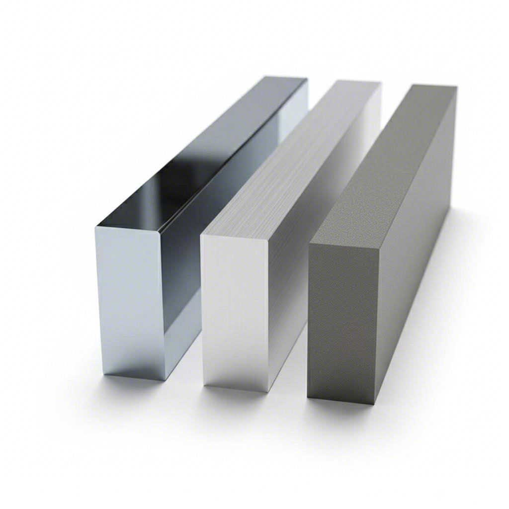
Choosing the right aluminum alloy isn't just a technical checkbox—it's a decision that cascades through every aspect of your aluminum extrusion profiles, from achievable geometries to final surface quality. Get this wrong, and you'll fight manufacturing constraints throughout production. Get it right, and your design possibilities expand dramatically.
The 6xxx series alloys dominate extrusion applications for good reason. These aluminum-magnesium-silicon alloys offer an exceptional balance of extrudability, mechanical properties, and corrosion resistance. But within this family, three workhorses handle the vast majority of projects: 6063, 6061, and 6005A. Understanding their distinct personalities helps you match material capabilities to your specific requirements.
Think of 6063 as the architectural darling of aluminium extrusion profiles. When your project demands flawless surface finish—window frames, decorative trim, consumer electronics housings—6063 delivers. Its excellent extrudability means manufacturers can push material through intricate dies with thinner walls and tighter corner radii than stiffer alloys allow. The tradeoff? Lower tensile strength compared to its structural cousins.
Need to bear serious loads? That's where 6061 steps in. Structural aluminium extrusions for aerospace, marine, and heavy equipment applications typically specify this workhorse alloy. Its higher strength comes with reduced extrudability, meaning your design may require slightly thicker walls and more generous corner radii. Welding 6061 also demands more attention—the heat-affected zone loses significant strength unless you plan for post-weld heat treatment.
6005A occupies the strategic middle ground that many designers overlook. When 6063 isn't quite strong enough but 6061's processing constraints feel too limiting, this alloy often provides the sweet spot. Rail car manufacturers and structural framing applications frequently leverage 6005A for exactly this balance.
| Property | 6063-T6 | 6061-T6 | 6005A-T6 |
|---|---|---|---|
| Tensile Strength (MPa) | 215 | 310 | 270 |
| Extrudability Rating | Excellent | Fair | Good |
| Corrosion Resistance | Excellent | Good | Very Good |
| Weldability | Excellent | Good (strength loss) | Good |
| Typical Applications | Architectural, decorative, heat sinks | Structural, aerospace, marine | Rail, structural framing, transport |
Here's what competitor content rarely explains: your alloy selection directly constrains your geometric possibilities. Higher-strength alloys resist flowing through complex die openings. This resistance translates into real design limitations you'll need to accommodate.
With 6063, you can confidently design wall thicknesses approaching 1.0mm in many profile configurations. The material flows smoothly, fills intricate details completely, and emerges with surfaces ready for anodizing or powder coating with minimal preparation. This makes 6063 ideal for the diverse types of aluminum extrusions seen in architectural applications.
Specify 6061, and your minimum practical wall thickness may need to increase to 1.5mm or more, depending on profile complexity. Corner radii requirements grow more generous. The material's higher flow stress means dies work harder, wear faster, and may struggle to fill sharp internal features completely.
Surface finish quality follows a similar pattern. Types of aluminum extrusion alloys with better flow characteristics—like 6063—naturally produce smoother surfaces with fewer die lines and surface imperfections. When aesthetics matter, this difference becomes visible in the final product.
The practical takeaway? Always validate your alloy selection against your geometric requirements early in design. A profile that extrudes beautifully in 6063 may prove problematic or impossible in 6061. Your manufacturer can provide alloy-specific design guidance, but only if you engage them before finalizing specifications.
You've selected your alloy—now comes the question that makes or breaks your aluminum extrusion shapes: how thin can you actually go? Wall thickness might seem like a simple specification, but it represents the intersection of structural engineering, metallurgical behavior, and die manufacturing reality. Get the numbers wrong, and you'll face rejected designs, costly die modifications, or profiles that warp and twist during cooling.
Unlike generic guidance that simply tells you "thinner is harder," you need specific numbers to work with. So let's get practical about what your manufacturer can actually achieve—and what your application genuinely requires.
For standard solid and semi-hollow extruded aluminum shapes, minimum wall thickness typically ranges from 1.0mm to 1.5mm. But here's the nuance most resources skip: this range shifts based on your profile's overall size and geometric complexity.
The critical relationship involves something called the circumscribing circle diameter (CCD)—essentially, the smallest circle that completely contains your profile's cross-section. Larger profiles with bigger circumscribing circles can support proportionally thinner walls because the die has more structural support and metal flows through a larger opening with less resistance.
Consider these practical guidelines for aluminum extruded shapes:
Hollow sections—those alum extrusion shapes with enclosed voids—require special consideration. The die construction needed to create internal cavities (using a mandrel or porthole die) limits how thin adjacent walls can be. Plan for minimum wall thicknesses 20-30% greater than equivalent solid sections would require.
Extruded aluminum channel shapes and other semi-hollow profiles fall somewhere between. That partially enclosed channel creates manufacturing challenges similar to fully hollow sections but typically allows slightly thinner walls than complex multi-void designs.
When you're planning extruded shapes, wall thickness decisions must satisfy multiple masters simultaneously. Understanding these competing factors helps you find the practical sweet spot:
Here's a critical design principle: uniform wall thickness dramatically improves your outcomes. When aluminum flows through a die, it naturally moves faster through larger openings. Variable wall thicknesses create differential flow rates, leading to profile distortion, internal stresses, and accelerated die wear.
When your design absolutely requires varying wall thicknesses—and many functional profiles do—you'll need thoughtful transition design. Gradual tapers between thick and thin sections help equalize flow rates. Abrupt transitions create flow disruptions and stress concentrations in both the die and the finished profile.
The maximum-to-minimum wall thickness ratio provides a practical guardrail: keep this ratio at 3:1 or less whenever possible. A profile with 3mm walls in one area and 1mm walls elsewhere represents the practical limit. Exceed this ratio, and you'll face uneven cooling that causes warping, twisting, and dimensional instability that no amount of post-processing can fully correct.
Knowing your wall thickness constraints lets you optimize profile geometry—but geometry alone doesn't guarantee a successful part. Tolerances determine whether your beautifully designed profile actually fits and functions in assembly, a topic that demands equally specific numerical guidance.
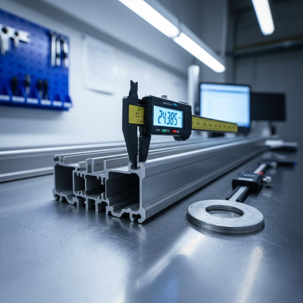
So your wall thicknesses are optimized and your geometry looks perfect on screen—but will the finished profile actually fit your assembly? This is where aluminum extrusion tolerances become the difference between smooth production and frustrating rework. Tolerances define the acceptable variation in your extruded aluminum sizes, and specifying them correctly requires understanding what's achievable, what's necessary, and what each tighter specification actually costs you.
Here's the uncomfortable truth: many designers default to the tightest tolerances available, assuming precision always equals quality. In reality, over-specifying tolerances inflates costs without improving function. Under-specifying leads to assembly nightmares. Finding the right balance demands specific knowledge about aluminum extrusion dimensions and how they behave across different profile types.
Industry tolerance standards—most commonly referenced from the Aluminum Association in North America or EN standards in Europe—establish baseline expectations for extruded aluminum sections. These standards define multiple tolerance classes, typically ranging from "standard" to "precision" grades, with each step representing tighter dimensional control and increased manufacturing complexity.
Standard tolerances accommodate the natural variation inherent in the extrusion process: thermal expansion during cooling, minor die wear, stretching operations, and material flow characteristics. Precision tolerances require additional process controls, more frequent die maintenance, slower production speeds, and often secondary machining operations.
| Tolerance Type | Standard Tolerance (Metric) | Precision Tolerance (Metric) | Standard Tolerance (Inch) |
|---|---|---|---|
| Cross-sectional dimensions | ±0.25mm to ±0.60mm | ±0.10mm to ±0.25mm | ±0.010" to ±0.024" |
| Wall thickness | ±0.15mm to ±0.40mm | ±0.08mm to ±0.20mm | ±0.006" to ±0.016" |
| Straightness (per meter) | 0.5mm to 1.5mm | 0.25mm to 0.5mm | 0.020" to 0.060" per 3ft |
| Twist (degrees per meter) | 1° to 3° | 0.5° to 1° | 1° to 3° per 3ft |
| Flatness (across width) | 0.3% to 0.5% of width | 0.15% to 0.25% of width | 0.003" to 0.005" per inch |
| Angular dimensions | ±1° to ±2° | ±0.5° to ±1° | ±1° to ±2° |
Notice how tolerance values scale with feature size—larger aluminum extrusion dimensions naturally carry larger absolute tolerances. A 100mm-wide aluminum section might allow ±0.45mm variation under standard tolerances, while a 25mm dimension on the same profile permits only ±0.25mm. This proportional relationship reflects the physics of metal flow and cooling behavior.
When should you specify tighter controls? Consider precision tolerances when:
Not all dimensions on your profile carry equal importance. Identifying which aluminum extrusion sizes truly matter—and which can accept standard tolerances—separates cost-effective specifications from expensive over-engineering.
Flatness becomes critical for profiles serving as mounting surfaces or requiring consistent contact along their length. Wide, thin-walled sections are particularly susceptible to flatness deviation because differential cooling creates internal stresses. If your design includes broad flat surfaces, expect to either accept looser flatness tolerances or budget for additional straightening operations.
Twist affects profiles with asymmetric cross-sections more severely than balanced shapes. Long, thin extruded aluminum sections—particularly those with uneven wall distribution—may develop helical distortion during cooling. Controlling twist often requires slower extrusion speeds and careful quench management, adding cost to every foot produced.
Straightness matters most for structural applications and assemblies requiring long unsupported spans. Standard straightness tolerances work fine for profiles cut into shorter lengths, but full-length architectural applications may demand precision control.
Angular dimensions—the actual angles formed between profile surfaces—deserve attention when your design relies on specific geometric relationships. Corner angles in framing systems, V-groove channels, and interlocking profiles all require angular accuracy for proper function.
Several factors influence what tolerances your manufacturer can realistically achieve:
The cost implications are real and cumulative. Each step from standard to precision tolerances might add 15-30% to your per-piece cost through slower production, increased inspection, higher rejection rates, and additional processing. Specify precision only where function demands it, and accept standard tolerances everywhere else.
One final note: metric and inch-based tolerance systems don't convert directly. Standards developed independently, reflecting different manufacturing traditions and measurement practices. When working with international suppliers or specifying for global production, confirm which tolerance system applies and verify that your dimensional requirements translate correctly between systems.
With dimensional accuracy defined, your profile geometry takes shape—but those corners and transitions you've specified need equally careful attention to ensure both manufacturability and performance.
Those sharp corners on your CAD model look clean and precise—but they're likely creating problems you won't discover until production begins. Corner radii represent one of the most overlooked aspects of aluminum extrusion design guidelines, yet they directly influence die longevity, surface quality, and even structural performance. Unlike wall thickness or tolerances where some flexibility exists, corner design follows physical rules that manufacturers cannot simply engineer around.
When aluminum flows through a die, it behaves like a viscous fluid navigating obstacles. Sharp internal corners create dead zones where metal stagnates, struggles to fill completely, and generates tremendous stress on the die steel. Understanding the specific radius requirements—and why they exist—helps you design extrusion shapes that manufacture efficiently while performing reliably.
Here's the quantified guidance most aluminum extrusion design guides fail to provide: internal corners require radii of at least 0.5mm to 1.0mm as an absolute minimum. But that's just the floor. For optimal results, your internal corner radii should equal or exceed the adjacent wall thickness.
Why does wall thickness matter? Thicker walls carry more material volume flowing past each corner. That increased material flow demands smoother transitions to prevent turbulence, incomplete fills, and excessive die wear. A profile with 2mm walls benefits from 2mm internal radii—not because 1mm wouldn't technically extrude, but because the larger radius ensures consistent quality across production runs.
Consider the practical implications for your extruded shape designs. A complex profile with multiple internal corners at minimum radii will extrude more slowly, require more frequent die maintenance, and show greater piece-to-piece variation than an equivalent design with generous radii. The manufacturing cost difference compounds over production volume.
External corners follow different rules. Sharp external corners are technically achievable because the die simply ends at that point—there's no enclosed space for material to navigate. However, even external corners benefit from small radii (0.25mm to 0.5mm) that improve die durability and reduce the risk of edge chipping during handling.
The distinction between internal and external corners goes beyond manufacturing ease—it affects how your extruded structural aluminum performs under load. Internal corners with insufficient radii become stress concentration points where cracks initiate under cyclic loading or impact. External sharp corners create handling hazards and complicate finishing operations.
When your design absolutely requires a functionally sharp internal corner—perhaps to mate with a square-edged component—consider the dogbone approach. This technique removes a small circular pocket at the corner intersection, typically with a minimum radius of 0.5mm according to manufacturing guidelines. The result appears sharp from outside while providing the internal relief the extrusion process demands.
Adhering to corner design best practices delivers multiple benefits throughout your product lifecycle:
The structural performance implications deserve emphasis. When loads apply to extruded structural aluminum profiles, stress flows through the material like water through channels. Sharp corners create bottlenecks where stress intensity multiplies—sometimes by factors of 2x to 3x compared to the nominal applied stress. Rounded corners spread these loads across larger material volumes, dramatically improving resistance to both static overload and fatigue failure.
Post-processing operations also interact with your corner decisions. If your profile requires CNC machining after extrusion, matching internal corner radii to standard end mill diameters eliminates tedious cleanup passes. A 3mm internal radius works beautifully with a 6mm end mill; a 2.7mm radius requires either a smaller tool with multiple passes or leaves unmachined material in corners.
Powder coating and painting benefit from radii as well. Coatings naturally thin at sharp edges and build excessively in tight internal corners—phenomena called "edge pull" and "pooling." Profiles designed with appropriate radii receive more uniform coating thickness, improving both appearance and corrosion protection.
With corners properly designed, your profile geometry approaches completion—but thermal management applications introduce an entirely different set of design considerations that can make or break heat dissipation performance.

When electronics generate heat, that thermal energy needs somewhere to go—and aluminum profile extrusion offers design possibilities that other manufacturing methods simply cannot match. The same process that creates structural framing and architectural trim also produces the intricate finned geometries that keep processors cool, LED arrays bright, and power electronics functioning reliably. But designing heat sinks requires thinking beyond structural considerations into the physics of thermal transfer.
What makes extrusion particularly powerful for thermal applications? You can create fin densities, aspect ratios, and surface areas that would be prohibitively expensive—or outright impossible—with machining, casting, or stamping. A single extrusion pass produces complex aluminum extrusions shapes with dozens of precisely spaced fins, ready for cutting to length and immediate use.
Fin geometry drives heat sink performance more than almost any other factor. The goal is maximizing surface area for heat transfer while ensuring adequate airflow between fins. Get this balance wrong, and your beautifully finned profile becomes a thermal bottleneck rather than a cooling solution.
Fin height-to-gap ratios require careful optimization based on your cooling method. For natural convection applications—where heat rises without fan assistance—fin spacing should be at least 4mm to allow air to flow smoothly between fins. Tighter spacing actually reduces performance because boundary layers from adjacent fins overlap, choking airflow. Those sleek, tightly-packed fins might look impressive, but they'll underperform compared to properly spaced alternatives.
Forced convection changes the equation dramatically. When fans push air across your heat sink, you can pack fins more densely because the increased air velocity overcomes boundary layer effects. This allows fin spacing as tight as 1.5-2mm in high-airflow applications, substantially increasing surface area and heat dissipation capacity.
Fin thickness presents its own tradeoffs. Thicker fins conduct heat more effectively from base to tip but reduce the number of fins you can fit in a given width. Thinner fins maximize fin count and surface area but may create temperature gradients where fin tips remain cooler than bases—reducing effective heat transfer. Most custom aluminum extrusion profiles for thermal applications use fin thicknesses between 1.0mm and 2.5mm, balancing these competing factors.
Base thickness deserves equal attention. The base serves as the primary heat spreader, conducting thermal energy from your concentrated heat source across the full width of the fin array. According to thermal design principles, the base should be thicker at the heat source and gradually thinner toward the edges, optimizing heat distribution while minimizing unnecessary material mass.
Beyond fin design, several factors influence how effectively your alu extrusion profile manages heat. Understanding these variables helps you make informed design decisions:
The anodizing question deserves deeper exploration. While anodizing boosts emissivity for improved radiation, it also adds a thin aluminum oxide layer with lower thermal conductivity than base aluminum. For natural convection heat sinks where radiation matters, anodizing typically provides net benefit. For forced convection applications where air-side heat transfer dominates, the added thermal resistance may slightly reduce performance—though the corrosion protection and aesthetic benefits often justify the minor tradeoff.
Large aluminium extrusions for high-power applications introduce additional considerations. When heat sinks must dissipate hundreds of watts, base thickness and fin height both increase substantially. These larger profiles may require multiple mounting points, structural reinforcement, and careful attention to thermal expansion during temperature cycling.
What happens when your heat sink must also bear mechanical loads? This dual-function requirement appears frequently in LED lighting fixtures, motor housings, and electronics enclosures. The same profile that dissipates heat may simultaneously support weight, resist vibration, or provide structural rigidity.
Designing for combined thermal and structural functions demands balancing competing requirements. Fin geometries optimized purely for cooling may lack the stiffness needed for structural applications. Wall thicknesses adequate for heat spreading may exceed structural requirements, adding unnecessary weight. The solution often involves integrating structural ribs or thickened sections away from the primary fin array—using extrusion's geometric flexibility to satisfy both thermal and mechanical demands within a single profile.
When specifying thermal extrusions, remember that fin configuration significantly impacts both performance and manufacturability. Rectangular fins extrude most easily and provide predictable thermal behavior. Pin fins—though excellent for omnidirectional airflow—require more complex dies and typically higher minimum order quantities. Your choice should reflect both thermal requirements and practical manufacturing constraints.
Thermal design sets the stage for how your profile performs—but even the best heat sink design fails if it can't connect properly to surrounding components. Joint design and assembly integration demand equally careful consideration to ensure your profiles work within complete systems.
Your aluminum profile might perform flawlessly in isolation—but products don't exist in isolation. They connect, fasten, interlock, and integrate with other components. If you haven't designed your extrusion with assembly in mind from day one, you'll discover costly surprises when production meets reality. Retrofit solutions rarely work as elegantly as features designed into the original profile.
Think about it this way: every connection point represents a potential failure mode, a tolerance stack-up challenge, and a manufacturing cost driver. Aluminum extrusion assembly succeeds when profile geometry anticipates exactly how components will join together—whether through mechanical fasteners, welding, adhesives, or clever interlocking features that snap into place without additional hardware.
Mechanical fastening remains the most common joining method for structural extruded aluminum applications, and your profile design directly determines how efficiently fasteners can be installed. Random screw holes drilled as an afterthought create weak points and add secondary operations. Integrated fastening features designed into the extrusion eliminate these problems entirely.
If you've worked with 8020 extrusion systems or similar modular framing, you've seen T-slot design at its most refined. These channels accept sliding nuts, brackets, and connectors at any position along the profile length—no drilling required. The genius lies in the geometry: a narrow slot opening that captures fastener heads while the wider internal channel provides clearance for insertion and sliding adjustment.
Building with aluminum extrusion becomes remarkably flexible when T-slots are incorporated thoughtfully. Consider where connections will occur and orient slots accordingly. Profiles with slots on all four sides maximize configuration options but may sacrifice structural efficiency. Profiles with slots only where needed maintain strength while still enabling modular assembly.
Beyond T-slots, several connection design features can be integrated directly into your extrusion geometry:
For any aluminum extrusion builder developing modular systems, these integrated features transform assembly from a labor-intensive process into a streamlined operation. The upfront die investment pays dividends across every unit produced.
When mechanical fastening won't satisfy your structural or aesthetic requirements, welding and adhesive bonding offer permanent joining alternatives—but each demands specific design accommodations.
Weld preparation starts at the extrusion design stage. Joint configurations that work beautifully for steel often fail with aluminum. You'll need adequate material thickness at weld zones—typically 1.5mm minimum, with 2mm or more preferred for structural welds. Corners benefit from small radii that facilitate complete weld penetration without burn-through.
Alloy selection directly impacts weldability. Remember the 6063 versus 6061 discussion from alloy selection? Here's where it matters most. 6063 welds more easily with less tendency toward cracking, making it preferable for aluminum extrusion projects requiring extensive welded assemblies. However, the heat-affected zone in welded 6063 drops to roughly 50% of its T6 temper strength.
6061 presents a more complex picture. While weldable, it requires more careful heat input control and may demand post-weld heat treatment to restore full strength in critical structural applications. The higher base strength sometimes justifies this additional processing, but your design must account for either the strength reduction or the added heat treatment step.
Adhesive bonding has gained significant traction for joining structural extruded aluminum, particularly where fatigue resistance, vibration damping, or dissimilar material joining matter. Design for adhesive joints focuses on maximizing bond area and ensuring consistent gap control. Integrate bonding flanges or surfaces into your profile geometry—flat, parallel surfaces with enough width to achieve required bond strength.
Tolerance requirements at mating surfaces deserve special attention regardless of joining method. Assembly stack-up accumulates dimensional variation from every component in your system. If three profiles must align precisely, their combined tolerances determine whether assembly succeeds or requires shimming and adjustment.
Design for assembly stack-up by identifying critical alignment dimensions and specifying tighter tolerances only on those features. Allow looser tolerances elsewhere to control costs. Consider adjustment mechanisms—slotted holes, eccentric fasteners, or shimming provisions—that accommodate variation without compromising final assembly quality.
Joint design ultimately determines whether your beautiful extrusion profiles become functional products or frustrating assembly puzzles. Getting connections right from the design phase eliminates the costly rework that plagues projects where assembly was an afterthought—and sets the stage for optimizing the cost factors that determine your project's financial success.
Every design decision you make carries a price tag—some visible, others hidden until quotes arrive or production stumbles. Understanding the true aluminum extrusion cost drivers empowers you to make informed tradeoffs between performance requirements and budget constraints. The designers who consistently deliver cost-effective profiles aren't necessarily the most technically sophisticated; they're the ones who understand where money flows during manufacturing.
Here's what most resources won't tell you directly: cost optimization doesn't mean compromising quality. It means allocating your budget where it matters most while avoiding unnecessary expenses that add nothing to your product's function or appeal. Let's examine exactly how your design choices translate into manufacturing dollars.
Not all cost factors carry equal weight. When evaluating your design for cost efficiency, prioritize your attention according to actual financial impact:
Understanding this hierarchy helps you negotiate tradeoffs intelligently. Spending extra on die development to eliminate secondary machining often reduces total program cost. Accepting standard tolerances on non-critical dimensions while specifying precision only where function demands it optimizes your tolerance budget.
Standard aluminum extrusions offer a compelling cost advantage that custom designs cannot match: zero tooling investment. Before committing to custom development, evaluate whether existing standard shapes—channels, angles, tubes, and common architectural profiles—might satisfy your requirements. Even slight design modifications that align with standard aluminum extrusion tooling already in a manufacturer's library can eliminate thousands in die development costs.
The circumscribing circle diameter (CCD) directly influences both die cost and press capacity requirements. Larger profiles require larger dies, heavier presses, and more aluminum per linear foot. Whenever possible, minimize your CCD while maintaining required functionality. Sometimes repositioning features or adjusting proportions reduces CCD without affecting performance—delivering immediate cost savings.
Hollow versus solid profiles present an interesting economic equation. Hollow sections require porthole or bridge dies—significantly more complex and expensive than solid dies. A complex hollow aluminum extrusion die might cost three to five times more than a solid profile die of similar external dimensions. However, hollow sections use less material per foot, weigh less, and often provide superior structural efficiency through better moment of inertia distribution.
For extrusion examples that illustrate this tradeoff: a solid rectangular bar might require a $1,500 die but consume substantial aluminum. An equivalent hollow tube with comparable bending strength might need a $4,500 die but use 40% less material. At low volumes, the solid bar wins economically. At higher volumes, material savings from the hollow section eventually overcome the tooling premium. Your break-even volume depends on profile size, alloy cost, and annual consumption.
Minimum order quantities (MOQs) represent another cost lever. Custom dies typically require minimum runs of 500-2,000 pounds to justify setup and processing costs. Lower volumes face per-pound premiums or may be declined entirely. Design standardization across your product lines dramatically improves your ordering economics—using the same profile in multiple products increases your combined volume, reducing per-piece costs and improving supplier relationships.
Aluminum extrusion tooling longevity also factors into your cost calculations. Well-designed dies with appropriate wall thicknesses, generous radii, and balanced metal flow can produce millions of feet before replacement. Marginal designs with stress-concentrating features or unbalanced flow patterns may require replacement after much shorter runs—adding ongoing tooling expense that budget projections often miss.
The most cost-effective designs emerge when you engage manufacturers early, before finalizing specifications. Experienced aluminum extrusion die engineers can often suggest minor modifications that dramatically reduce tooling cost or improve production efficiency without compromising your functional requirements. This collaborative approach transforms the design phase from a cost-generation exercise into a cost-optimization opportunity.
With cost factors understood and optimized, your attention naturally turns to how those profiles will look and perform after surface treatment—decisions that must be made during design, not deferred until production begins.
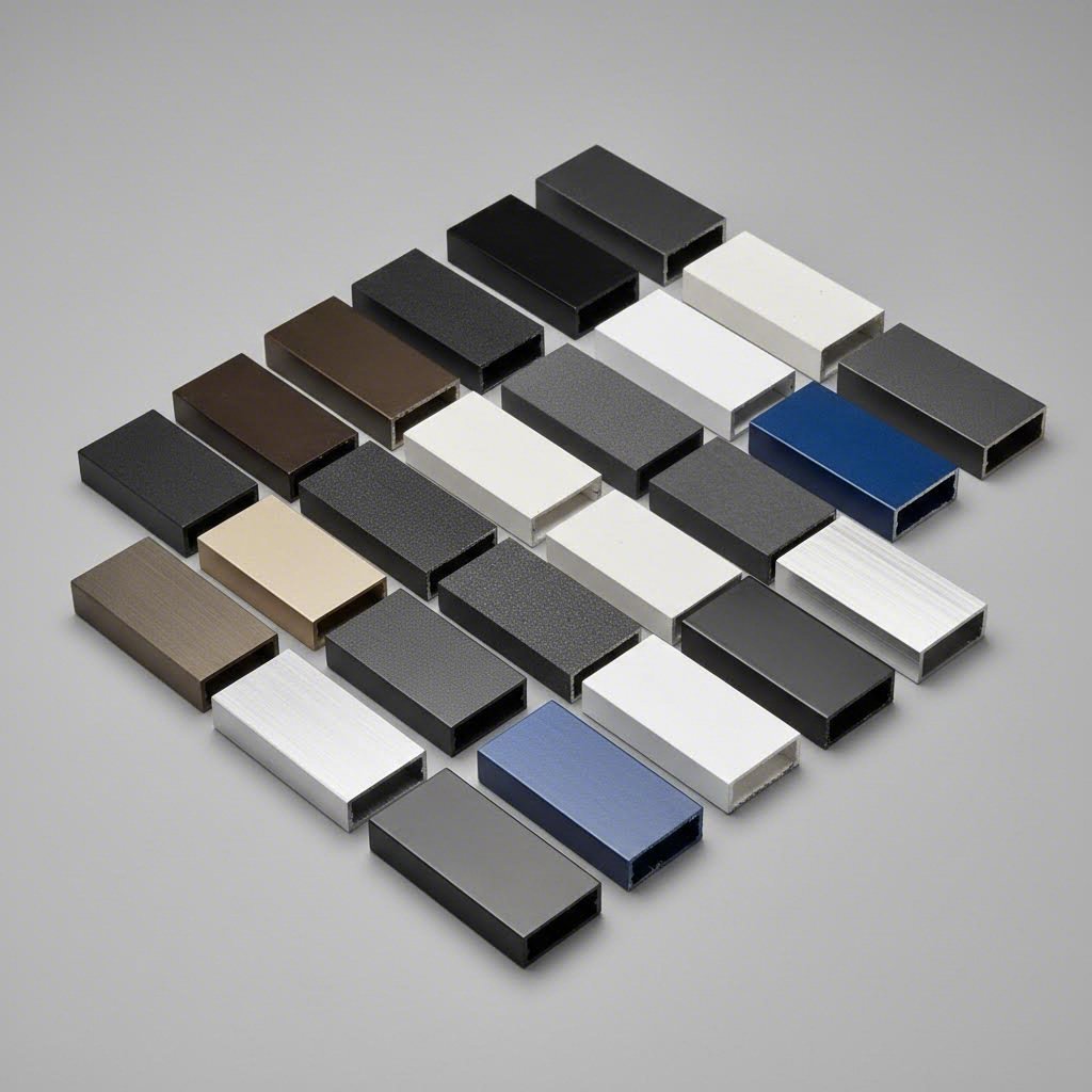
Your extruded profile emerges from the press with a functional but unfinished appearance—and the surface treatment you select will determine both its aesthetic appeal and long-term durability. Here's what catches many designers off guard: surface treatment isn't a decision you make after extrusion. It's a decision that must inform your profile geometry from the earliest design stages. The aluminium extrusion process creates shapes that interact differently with various finishing methods, and ignoring these relationships leads to coating failures, appearance defects, and costly rework.
Think about it practically. Anodizing builds an oxide layer that grows into the aluminum surface—meaning wall thickness variations create visible color differences. Powder coating flows and cures around your profile's geometry, pooling in tight corners and thinning over sharp edges. Each finishing method imposes its own design constraints that you'll need to accommodate or accept compromised results.
Anodizing remains the most popular finish for alu extrusion profiles, and for good reason. This electrochemical process converts the aluminum surface into a hard, corrosion-resistant oxide layer that accepts dyes for coloring. But uniform anodizing demands uniform material—consistent alloy composition, consistent wall thickness, and consistent surface preparation.
When designing custom extruded aluminum profiles destined for anodizing, pay special attention to wall thickness uniformity. Areas with different material thicknesses cool at different rates during extrusion, creating microstructural variations that anodize differently. The result? Visible banding, color streaking, or mottled appearance that no amount of process adjustment can fully eliminate. Keep your wall thickness ratio at 3:1 or less, and avoid abrupt transitions between thick and thin sections.
Powder coating offers more forgiving geometry requirements but introduces different constraints. During the coating process, profiles hang from racks and pass through spray booths and curing ovens. Your design must accommodate:
PVDF coatings—the premium choice for architectural applications demanding exceptional weathering resistance—share many constraints with powder coating but add stricter substrate preparation requirements. The extrusion aluminium process must produce surfaces smooth enough for proper adhesion, and profile geometry must allow complete coating coverage without shadowed areas.
Specialty finishes like micro-arc oxidation create exceptionally hard ceramic-like surfaces but require specific alloy compositions and profile geometries that support the high-voltage treatment process. These advanced finishes demand early coordination between design, extrusion, and finishing teams to ensure compatibility throughout the aluminium extrusion manufacturing process.
Beyond material considerations, your profile's shape directly influences finishing quality. The relationship between geometry and treatment outcomes follows predictable patterns—understanding these helps you design for finishing success.
| Surface Treatment | Durability | Relative Cost | Color Options | Key Design Requirements |
|---|---|---|---|---|
| Architectural Anodizing (Class I) | Excellent (20+ years exterior) | Medium | Limited (clear, bronze, black, champagne) | Uniform wall thickness; generous radii; consistent alloy |
| Hard Anodizing (Type III) | Exceptional wear resistance | High | Limited (typically dark gray/black) | Minimum 1.5mm wall thickness; avoid sharp internal corners |
| Powder Coating | Very Good (10-15 years exterior) | Medium-Low | Virtually unlimited RAL/custom colors | Hanging provisions; drainage paths; avoid deep recesses |
| PVDF/Kynar | Exceptional (30+ years exterior) | High | Wide range including metallics | Smooth surfaces; no oil contamination; uniform preparation |
| Micro-arc Oxidation | Exceptional hardness and corrosion resistance | Very High | Limited (white, gray, black) | Compatible alloy; adequate wall thickness; simple geometry |
Corner radii affect every finishing method differently. Anodizing builds uniformly around gentle curves but struggles to develop consistent thickness in sharp internal corners—leaving potential corrosion vulnerabilities. Powder coating thins dramatically over sharp external edges while building excessively in tight internal corners. The design guidance from earlier sections on corner radii applies doubly when surface treatment enters the equation.
For each extruded profile in your product line, document the intended surface treatment alongside geometric specifications. This ensures that tolerance callouts, corner radii, and wall thickness decisions align with finishing requirements—not just extrusion manufacturability.
Complex projects benefit enormously from working with manufacturers offering comprehensive capabilities spanning both extrusion and deep processing. Partners equipped with multiple surface treatment options—such as anodizing in custom colors like champagne and rose gold, powder coating, PVDF, and micro-arc oxidation—can evaluate your design holistically. Their technical teams identify potential finishing issues during die development rather than discovering problems after production begins.
This end-to-end approach proves especially valuable when your design pushes geometric limits or requires specialty finishes. Manufacturers with integrated extrusion presses, CNC machining centers, and finishing lines ensure your design intent carries through every production stage—from initial billet to finished product ready for assembly. The alternative—coordinating between separate extrusion suppliers and finishing houses—introduces handoff delays, quality variability, and finger-pointing when problems emerge.
Surface treatment selection completes the major design decisions for your aluminum extrusion—but translating these choices into successful production requires a systematic approach that captures every critical specification before die development begins.
You've absorbed the technical details—alloy properties, wall thickness limits, tolerance specifications, corner radii requirements, thermal considerations, joint design principles, cost drivers, and surface treatment constraints. Now comes the critical step that separates successful aluminum extrusion projects from expensive learning experiences: translating all that knowledge into a systematic review process before committing to die development.
Think of extrusion die design as a one-way door. Once you've approved tooling and production begins, changes become exponentially more expensive. A $2,000 design modification during the review phase might cost $20,000 after die construction—not counting production delays, scrapped material, and missed delivery commitments. The aluminium extrusion design guidelines you've learned only deliver value when applied systematically before that door closes.
Before releasing any profile aluminum extrusion design for tooling, walk through this sequential verification process. Each step builds on the previous ones, ensuring you've addressed interdependencies that single-issue reviews might miss:
This checklist functions as your aluminium design manual for pre-production verification. Document your review findings, noting any design compromises made and their rationale. This documentation proves invaluable when production questions arise months or years later.
Here's a truth that experienced engineers learn—sometimes painfully: your manufacturer isn't just a vendor executing your specifications. The right partner functions as an extension of your design team, identifying optimization opportunities and potential problems that even thorough self-review might miss.
What distinguishes manufacturers capable of genuine design collaboration from those who simply quote and produce? Look for these indicators:
Early engagement matters enormously. Sharing your design concepts during development—not after specifications are frozen—allows experienced manufacturers to suggest modifications that reduce die complexity, improve production efficiency, or enhance product performance. These suggestions cost nothing to implement during design but become increasingly expensive as projects progress.
The aluminum extrusion projects that deliver the best outcomes share a common pattern: designers who understood fundamental principles, applied systematic review processes, and collaborated with capable manufacturing partners from the earliest feasible stage. You now have the knowledge foundation. The systematic checklist provides your verification framework.
What remains is finding the right manufacturing partner—one with the technical depth, equipment range, and integrated capabilities to transform your optimized designs into finished products. For engineers and product designers seeking comprehensive aluminum extrusion and deep processing services, exploring manufacturers who offer end-to-end support from die development through surface treatment provides a starting point for that critical partnership.
The design principles you've learned throughout this guide—material selection, geometric optimization, tolerance specification, thermal management, assembly integration, cost awareness, and finishing compatibility—represent accumulated industry knowledge refined across countless projects. Apply them systematically, verify them thoroughly, and partner wisely. Your aluminum extrusion designs will reward you with reduced tooling costs, smoother production, and products that perform exactly as intended.
Key design considerations include alloy selection (6063 for aesthetics, 6061 for strength, 6005A for balance), wall thickness (typically 1.0-1.5mm minimum), corner radii (internal corners need radii equal to or greater than wall thickness), tolerance specifications, thermal management for heat sinks, joint design for assembly, and surface treatment compatibility. Design decisions made early lock in approximately 80% of manufacturing costs, making upfront planning essential for cost-effective production.
Minimum wall thickness typically ranges from 1.0mm to 1.5mm for standard profiles, depending on the circumscribing circle diameter (CCD). Small profiles under 50mm CCD require 1.2-1.5mm walls, medium profiles (50-150mm CCD) can achieve 1.0-1.2mm, and larger profiles may go as thin as 0.8-1.0mm. Hollow sections require walls 20-30% thicker than equivalent solid sections. Maintaining a maximum-to-minimum wall thickness ratio of 3:1 or less prevents cooling distortion.
Choose 6063 when surface finish and aesthetics are priorities—it offers excellent extrudability, allowing thinner walls and tighter corner radii, making it ideal for architectural applications and heat sinks. Select 6061 when higher tensile strength (310 MPa vs 215 MPa) is required for structural, aerospace, or marine applications. 6005A provides a middle-ground option with good strength and extrudability for rail and transport applications.
Internal corners require minimum radii of 0.5mm to 1.0mm, with optimal radii equal to or greater than the adjacent wall thickness. Sharp external corners are achievable but benefit from small radii (0.25-0.5mm) for die durability. Generous radii improve die life, reduce stress concentrations, enhance surface finish quality, and ensure uniform anodizing coverage. For functionally sharp internal corners, use the dogbone approach with circular relief pockets.
Reduce costs by minimizing circumscribing circle diameter, maintaining uniform wall thickness, specifying standard tolerances except where precision is functionally necessary, and using generous corner radii. Consider standard aluminum profiles before custom designs to eliminate tooling investment. Hollow sections cost more for dies but save material over production volume. Engage manufacturers early for design optimization suggestions, and standardize profiles across product lines to increase order volumes and improve pricing.



 Servicio en línea
 0086 136 3563 2360
 sales@sxalu.com
 +86 136 3563 2360
 español
 English
 français
 Deutsch
 русский
 português
 العربية
 ไทย
ไทย Việt
Việt Українська