When you hear the term aluminum airfoil extrusion, what comes to mind? If you're picturing aircraft wings, you're on the right track, but the architectural and industrial applications are where these profiles really shine. Let's break it down.
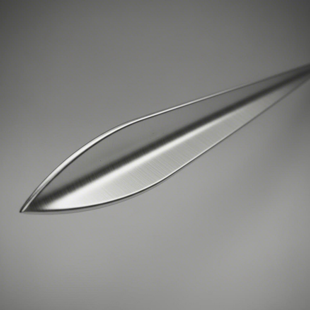
An aluminum airfoil extrusion is a continuous aluminum profile whose cross-section replicates an aerodynamic or blade-shaped geometry, characterized by a curved leading edge, tapered trailing edge, defined chord length, and optional camber.
In simpler terms, imagine slicing through an airplane wing and looking at the cut face. That teardrop-like shape, with its rounded front and pointed back, is what defines an airfoil. When manufacturers produce aluminum extrusions with this cross-sectional geometry, they create profiles optimized for managing airflow, controlling sunlight, or achieving sleek blade-like aesthetics in architectural designs.
The key geometric parameters that define an airfoil shape include:
These aluminum extrusion profiles can be symmetric, meaning identical curvature on both surfaces, or cambered, with different upper and lower surface shapes. Architectural applications often use cambered designs to optimize solar shading performance at specific blade angles.
How does an airfoil differ from the aluminum extrusion shapes you might find in a typical catalog? Standard structural extrusions like angles, channels, and tubes are designed primarily for load-bearing applications. Their geometry prioritizes structural efficiency, connection simplicity, and material economy.
Extrusion aluminum in airfoil form serves a different purpose. These profiles are optimized for:
One terminology note worth clarifying: you'll encounter several names for the same product category. Airfoil is the American English term, while aerofoil is the British English equivalent. Wing profile and blade extrusion are also used interchangeably in the industry. Whether you're searching for aluminium aerofoil extrusions or aluminum wing profiles, you're looking at the same fundamental product, just with regional naming variations.
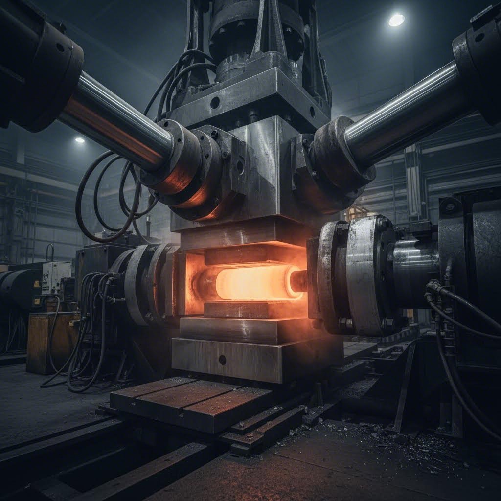
So how does a solid aluminum cylinder transform into that elegant blade-shaped profile? The aluminum extrusion process follows a straightforward principle: heat the metal, push it through a shaped opening, and cool it down. Sounds simple, right? For airfoil profiles, the execution gets considerably more nuanced.
The process begins with a cylindrical aluminum billet, typically heated to around 400-500°C. At this temperature, the metal becomes malleable without melting. A hydraulic ram in the aluminum extrusion press then forces this softened billet through a steel die, and out emerges a continuous profile matching the die's cross-sectional shape.
Here's the complete aluminum extrusion process broken down into stages:
The aluminum extrusion die is where the magic happens, and airfoil dies present unique challenges. Unlike a simple rectangular channel or round tube, an airfoil cross-section features asymmetric geometry with curved outer walls, varying thickness along the chord, and potentially internal webs or connector slots.
Why does this matter? The die must ensure balanced metal flow across the entire profile. If one section fills faster than another, you'll end up with uneven wall thickness, surface defects, or dimensional inaccuracies. For airfoil profiles, the curved leading edge and tapered trailing edge create natural flow imbalances that die designers must compensate for through careful inlet geometry and bearing length adjustments.
Complex airfoil shapes with internal webs or hollow sections require porthole dies, where the aluminum flows around mandrel supports and welds back together inside the die. This adds another layer of complexity to aluminum profile extrusion, as the weld seams must be invisible and structurally sound in the finished product.
Four critical variables determine whether your airfoil profile meets specification:
Billet temperature directly affects how easily the aluminum flows through the die. Too cold, and you'll need excessive force that risks cracking the billet or damaging the die. Too hot, and the metal may flow unevenly or develop surface defects. The aluminum extrusion machine monitors this carefully throughout production.
Press tonnage must match the profile's complexity and size. Airfoil profiles with longer chord lengths or thicker walls require higher tonnage to push the metal through the die at consistent speed. Industrial presses range from hundreds to thousands of tons of force.
Extrusion speed influences both surface quality and dimensional accuracy. Pushing too fast can cause surface tearing or uneven filling. Too slow, and the billet cools before completing the extrusion, leading to inconsistent properties along the profile length.
Quench rate locks in the profile's geometry and mechanical properties. Rapid cooling via water or forced air stabilizes the shape and prevents warpage, which is especially critical for airfoil profiles where even slight bow or twist affects fit-up in louver assemblies.
Alloy selection happens before the billet even enters the press, but it shapes everything that follows. 6063 aluminum is the go-to choice for architectural airfoil profiles because of its excellent extrudability and superior surface finish quality. When strength takes priority over aesthetics, 6061 offers better mechanical properties but requires more careful process control and produces a less refined surface. This alloy decision directly impacts what finishes you can apply later and how the profile performs in service.
Here's something most suppliers won't tell you upfront: the shape you draw on paper directly determines how much you'll pay for tooling. A simple symmetric airfoil with solid walls might cost a few hundred dollars to tool. Add internal webs, connector slots, or multiple hollow chambers, and that figure can climb into the thousands. Understanding this relationship helps you make smarter design decisions before committing to a custom aluminum extrusion.
Why does complexity matter so much? Every curve, cavity, and wall thickness variation in your aluminum extrusion profile requires corresponding features in the steel die. More features mean more machining time, tighter tolerances, and higher risk of die failure during production. Let's break down what drives these costs.
When die designers evaluate an airfoil profile, one of the first things they calculate is the tongue ratio. This is the ratio of a protruding feature's depth to its width. Imagine a thin fin extending from your airfoil's surface. If that fin is deep and narrow, it creates a high tongue ratio, which places significant stress on the corresponding section of the die.
Why should you care? High tongue ratios cause three problems:
Industry guidance suggests keeping tongue ratios below 3:1 whenever possible. For airfoil profiles with pronounced camber or deep trailing edges, this constraint can limit how aggressive your geometry can be without driving up tooling costs or requiring post-extrusion machining.
Wall thickness uniformity is equally critical. When you design an airfoil with thick leading edges and thin trailing sections, the aluminum flows at different speeds through those regions. Thick areas fill faster because they offer less resistance. This velocity mismatch causes differential cooling after the profile exits the die, which introduces bow or twist in the finished part. For louver and curtain wall applications where straightness tolerances are tight, even minor warpage can cause assembly headaches.
The practical fix? Keep wall thickness variation to a ratio of 2:1 or less across the section. If your design requires thicker regions for structural reasons, use gradual transitions rather than abrupt steps. This helps balance metal flow and reduces the risk of distortion.
Two geometric parameters have outsized influence on what your custom aluminum extrusions will cost: chord length and camber ratio.
Chord length, the straight-line distance from leading to trailing edge, determines how large your die needs to be. Longer chords require larger die blocks, which consume more raw steel and demand more machining time. More importantly, longer profiles need higher press tonnage to push the aluminum through at consistent speed. If your chord length exceeds what a standard press can handle, you'll need access to specialized high-tonnage equipment, which limits your supplier options and typically increases cost.
Camber ratio, the depth of curve relative to chord length, affects die complexity in a different way. A symmetric airfoil with no camber is relatively straightforward to tool. Add pronounced camber, and the die must accommodate asymmetric metal flow paths. The aluminum traveling along the more curved surface takes a longer path than metal on the flatter side, creating flow imbalances that die designers must compensate for through careful inlet geometry and bearing length adjustments.
For hollow airfoil profiles, like an aluminum extrusion tube with an aerodynamic cross-section, complexity increases further. These require porthole dies with mandrels and bridges to form the internal cavity. Each internal web or connector slot adds another element that must be precisely machined and balanced for uniform flow.
The table below maps how profile complexity affects your tooling investment. These are relative comparisons to help you understand trade-offs, not absolute pricing:
| Profile Complexity | Relative Tooling Cost | Typical Lead Time | Minimum Order Considerations |
|---|---|---|---|
| Simple solid airfoil | Low ($300-$800) | 7-10 days | Lower MOQ acceptable; die amortizes quickly |
| Hollow with internal webs | Medium ($800-$2,000) | 10-15 days | Moderate MOQ needed to justify tooling |
| Complex multi-void or T-slot | High ($2,000-$5,000+) | 15-20 days | Higher MOQ required; consider die amortization |
What does this mean for your project? If you're specifying custom aluminum extrusions for a small production run, a simpler solid profile might deliver 80% of the performance at 30% of the tooling cost. For high-volume applications where the die cost amortizes across thousands of meters of profile, investing in a more complex hollow design may make economic sense.
The key is matching your geometric requirements to realistic tooling constraints early in the design process. Once you understand how tongue ratio, wall uniformity, chord length, and camber interact with die feasibility, you can make informed trade-offs that balance performance against budget and lead time.
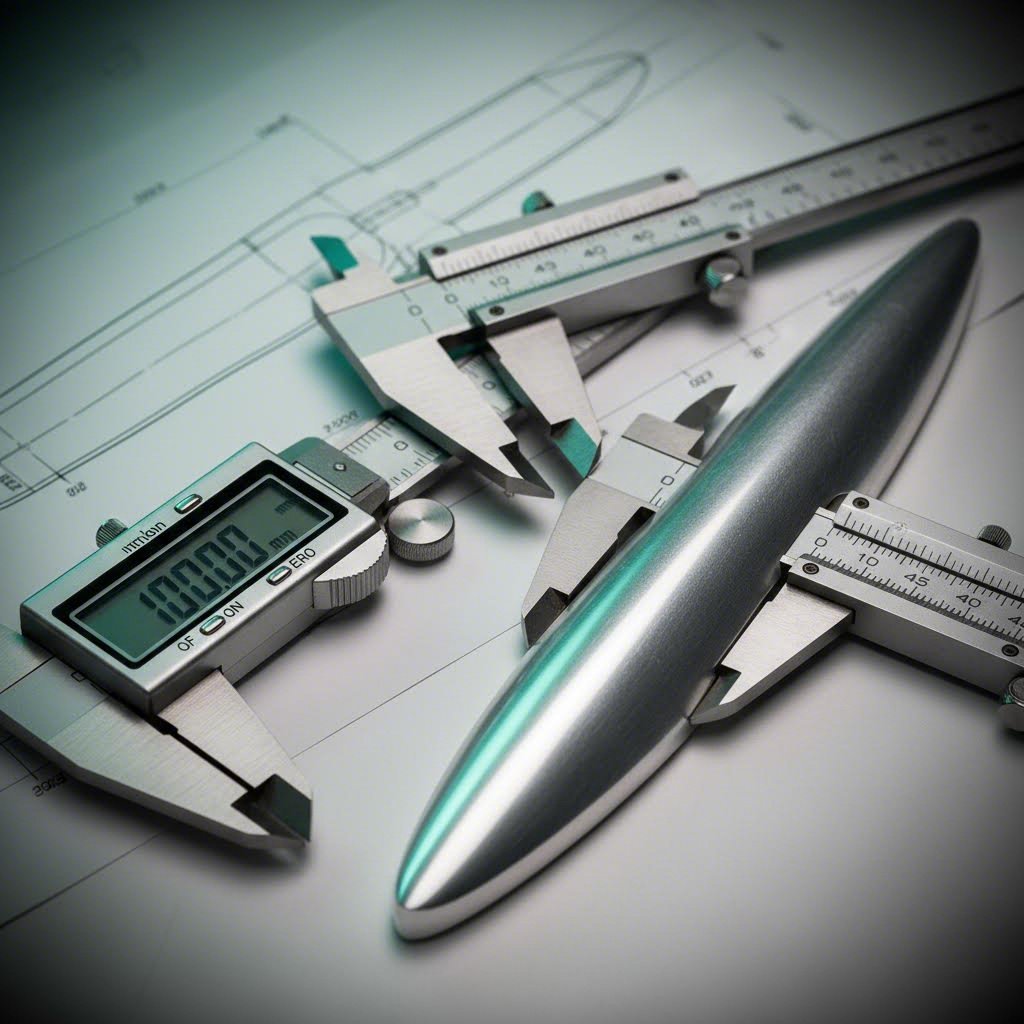
You've got your airfoil geometry figured out and understand how die complexity affects cost. Now comes the part that separates a successful specification from an expensive headache: nailing down the dimensional parameters and selecting the right temper. Skip this step, and you'll end up with profiles that don't fit, assemblies that won't align, or material properties that fall short of your application requirements.
When you browse an aluminum extrusion profiles catalog or request quotes from suppliers, you'll notice that standard aluminum extrusions come with published tolerances. Airfoil profiles follow the same tolerance frameworks, but their curved geometry introduces nuances that flat-faced profiles don't have. Let's walk through what you need to specify.
Before contacting any supplier, you'll want to define these critical geometric parameters:
Industry standards published by The Aluminum Association and ANSI provide baseline tolerances for aluminum profiles extrusion. These standards account for the circumscribing circle diameter, which is the smallest circle that can fully contain your profile's cross-section. Larger circumscribing circles generally mean looser standard tolerances.
For airfoil profiles, some practical rules of thumb apply. Wall thickness typically holds to approximately +/- 10% of nominal. Straightness runs around 0.0125 inches per foot of length. Twist tolerance sits at roughly 0.5 degrees per foot. These are achievable with standard aluminum extrusion sizes and processes, but your specific geometry may require tighter control.
Here's where cost enters the picture: tighter tolerances increase die cost and may require secondary aluminum extrusion machining operations. When you specify tolerances beyond standard capabilities, the extruder may need to modify dies, slow production speeds, increase inspection frequency, or accept higher rejection rates. All of this adds cost. The practical approach? Specify tight tolerances only where fit, form, or function genuinely requires them. For dimensions that don't affect assembly or performance, standard tolerances usually suffice.
One insight that can save you significant tooling investment: profile family variants. A single airfoil die can often be adapted to produce multiple related profiles. Imagine you need the same basic airfoil shape but with different wall thicknesses for different applications, or with optional internal webs for added stiffness, or with integrated connector slots for specific mounting systems. Rather than commissioning separate dies for each variant, an experienced extruder can sometimes modify a base die to accommodate these variations. This approach lets you leverage one tooling investment across multiple product lines, similar to how 2020 aluminum extrusion dimensions serve as a platform for countless accessories and configurations in modular framing systems.
Once you've locked in geometry and tolerances, the next decision is temper. This choice directly affects mechanical properties, cost, lead time, and dimensional stability. For airfoil profiles, three tempers dominate: T5, T6, and T52.
What's the difference? It comes down to heat treatment after extrusion.
T5 temper means the profile was air-quenched directly at the press exit and then artificially aged. There's no separate solution heat treatment step. This makes T5 faster and cheaper to produce. The resulting material has medium strength and hardness but retains good formability. For architectural louvers, decorative screens, and applications where appearance matters more than structural performance, T5 delivers excellent value.
T6 temper adds a solution heat treatment step before aging. The profile is heated above 500°C to dissolve alloying elements uniformly, then rapidly quenched in water, and finally artificially aged at 150-200°C. This two-step process produces significantly higher strength and hardness than T5. The trade-off? Longer lead time, higher cost, and reduced ductility. T6 is the right choice when your airfoil profile must carry structural loads or withstand demanding service conditions.
T52 temper is less commonly discussed but valuable for tight-tolerance applications. After extrusion and quenching, T52 profiles undergo stress relief by controlled stretching. This process removes residual stresses that can cause distortion during subsequent machining or over time in service. For airfoil profiles destined for curtain wall systems or precision louver assemblies where dimensional stability is critical, T52 offers better long-term straightness than T5 or T6.
| Property | T5 | T6 | T52 |
|---|---|---|---|
| Strength Level | Medium | High | Medium |
| Hardness | Medium (9-12 HW) | High (12-15 HW) | Medium |
| Relative Cost | Lower | Higher | Moderate |
| Lead Time Impact | Faster | Longer | Moderate |
| Dimensional Stability | Good | Good | Excellent |
| Best-Fit Applications | Architectural, decorative, interior | Structural, aerospace, high-load | Precision assemblies, tight-tolerance fit-up |
How do you choose? Start with your application requirements. If the airfoil profile serves a purely aesthetic or shading function with minimal structural demand, T5 keeps costs down and simplifies production. If the profile must resist significant loads, vibration, or impact, T6 provides the mechanical performance you need. If your assembly tolerances are exceptionally tight and you can't afford any post-installation warpage, T52 is worth the modest cost premium.
With dimensions, tolerances, and temper defined, you've completed the core specification work. The next consideration is surface finish, which presents its own set of challenges when applied to curved airfoil geometry.
Here's where airfoil profiles get tricky: they have no flat faces. Every surface curves, tapers, or transitions into another contour. This geometry creates unique challenges when applying protective finishes, and understanding these challenges helps you specify the right coating for your application without costly surprises during production.
Four primary finish options dominate the aluminum extrusion services landscape for airfoil profiles: anodizing, powder coating, PVDF coating, and micro-arc oxidation. Each brings distinct advantages and limitations, particularly when applied to curved blade geometries. Let's examine what makes each finish perform differently on these complex shapes.
Imagine trying to spray paint a teardrop shape evenly. The rounded leading edge faces the spray gun directly, while the tapered trailing edge angles away. The curved upper and lower surfaces present constantly changing angles to the coating equipment. This is exactly what finishers face with every airfoil profile.
For powder coating, the electrostatic application process relies on charged particles adhering to grounded aluminum. On flat surfaces, this produces uniform coverage. On curved airfoil geometry, several complications arise:
Anodized aluminum extrusions face different challenges. The anodizing process involves immersing profiles in acid baths where an electrochemical reaction builds up an oxide layer. For airfoil shapes, bath drainage becomes critical. If solution pools in curved sections during rinsing, it can cause streaking or uneven oxide thickness. Proper racking orientation and drainage time become more important than with simple rectangular profiles.
PVDF coating, applied as a liquid spray, shares some challenges with powder coating but offers better flow characteristics that help even out thickness variations on curved surfaces. The thin, uniform coating maintains crisp profile edges better than thicker powder applications.
Micro-arc oxidation uses plasma discharge in an electrolyte bath to create a ceramic-like surface layer. The process naturally produces more uniform coverage on complex geometries because the plasma seeks out the entire surface rather than relying on line-of-sight application.
Your installation environment should drive finish selection more than aesthetics alone. A black aluminum extrusion finish might look stunning in your design renderings, but if it's destined for a coastal facade, color retention matters more than initial appearance.
Anodizing works exceptionally well for interior applications and moderate exterior exposure. The oxide layer becomes integral to the aluminum surface, meaning it won't peel, chip, or delaminate like applied coatings can. Clear anodizing preserves the natural aluminum appearance, while color anodizing offers options including champagne, bronze, and rose gold tones. The limitation? Achieving consistent color across production batches requires tight control of alloy chemistry. Variations in magnesium or silicon content between billets can produce noticeable color shifts.
Powder coating delivers good UV resistance and the widest color range of any finish option. It's cost-effective for aluminum extrusion trim and decorative applications where exact color matching matters. The thicker coating layer also provides strong impact resistance, useful for profiles in high-traffic areas. However, that thickness can obscure fine profile details on intricate airfoil shapes, and the coating thickness variation on curved surfaces may be visible under certain lighting conditions.
PVDF coating represents the premium choice for demanding exterior environments. This fluoropolymer finish offers exceptional UV, humidity, and chemical resistance with outstanding color stability over decades. For coastal installations, high-UV desert climates, or any aluminum extrusion case where long-term appearance matters, PVDF justifies its higher cost through reduced maintenance and extended service life. The finish maintains color integrity with minimal chalking even after years of exposure.
Micro-arc oxidation produces a ceramic-like surface with excellent hardness and corrosion resistance. This finish suits demanding industrial environments where abrasion resistance and chemical exposure are concerns. The ceramic layer can withstand conditions that would degrade conventional coatings, making it ideal for HVAC applications or industrial blade systems exposed to harsh operating conditions.
| Finish Type | UV Resistance | Salt Spray Performance | Color Options | Cost Tier | Recommended Environment |
|---|---|---|---|---|---|
| Anodizing | Good | Moderate (500-1000 hrs) | Limited (clear, bronze, champagne, black) | Low-Medium | Interior, moderate exterior |
| Powder Coating | Good | Good (500-1500 hrs) | Extensive (RAL, custom match) | Low-Medium | Interior, general exterior |
| PVDF Coating | Excellent | Excellent (2000+ hrs) | Wide range with precise matching | High | Coastal, high-UV, harsh exterior |
| Micro-Arc Oxidation | Excellent | Excellent (2000+ hrs) | Limited (gray, black tones) | High | Industrial, high-wear applications |
Maintenance requirements vary significantly across these options. Anodized and PVDF-coated profiles typically need only periodic cleaning with mild detergent and water to maintain their appearance. Powder-coated surfaces may require more frequent inspection and occasional touch-up in high-exposure locations. Micro-arc oxidation surfaces are largely maintenance-free but offer limited aesthetic options.
When specifying finishes, consider the full lifecycle cost rather than just initial price. A PVDF finish might cost 30-50% more than powder coating upfront, but if it eliminates a recoating cycle fifteen years into the building's life, the total cost of ownership favors the premium option. With your surface finish selected, the next step is matching these specifications to your specific application requirements.
Now that you understand how to specify dimensions, tolerances, tempers, and finishes, the question becomes: which combination actually works for your project? The answer depends entirely on where and how the airfoil profile will be used. Different applications demand different trade-offs between strength, appearance, precision, and cost.
Rather than offering a vague list of possible uses, let's map specific application categories to the aluminum extrusions profiles and geometric parameters that actually perform in each context. This structured approach helps you match your project requirements to realistic specifications before engaging suppliers.
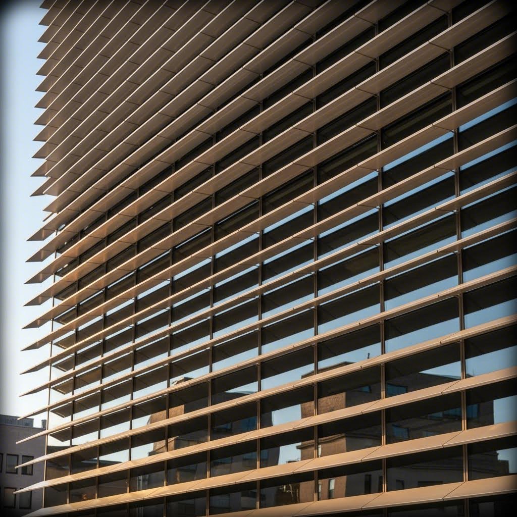
When you're designing a building facade with aluminum sun shade louvers, three geometric relationships determine whether your system actually controls solar heat gain: blade angle, chord length, and blade spacing.
Here's how they interact. Blade angle determines how much direct sunlight passes between adjacent blades at different sun positions throughout the day and year. A steeper angle blocks more high-angle summer sun but may obstruct views or reduce daylight penetration. Chord length affects how much shadow each blade casts on the one below it. Longer chords provide more shading depth but increase material cost and visual weight. Blade spacing, the gap between adjacent profiles, works with chord length to determine the shading coefficient, which quantifies how much solar radiation the system blocks.
The practical takeaway? Shading performance depends on these geometric relationships working together, not on any single parameter in isolation. When specifying louver systems, request shading coefficient data from suppliers based on your actual profile geometry and proposed blade spacing. Generic performance claims don't account for your specific design.
For most architectural louver applications, 6063-T5 aluminum delivers the right balance of extrudability, surface finish quality, and cost. The alloy produces smooth surfaces that accept anodizing and powder coating beautifully, and T5 temper provides adequate strength for blade spans up to several meters when properly supported. An optimal blade depth-to-spacing ratio of 1:1 achieves approximately 60% solar blockage, though your specific orientation and climate may require different proportions.
For large-span louvers exceeding 3 meters, consider profiles with continuous T-shaped stiffeners or edge hemming to prevent deformation under wind load. Material thickness of 2.5-3.0mm becomes important at these spans, and you'll want to maintain 5-8mm thermal expansion gaps between modules to accommodate seasonal movement.
Curtain wall applications place different demands on airfoil profiles than louver systems. Here, the aluminum extrusion frame must integrate precisely with glazing systems, and dimensional consistency across hundreds of meters of profile determines whether your facade assembles smoothly or requires costly field adjustments.
Tight straightness tolerances matter because airfoil profiles in curtain wall applications often serve as mullion caps, spandrel covers, or decorative blade elements that must align with glass panels and structural framing. When profiles arrive with bow or twist beyond specification, installers face the choice of forcing fit-up, which stresses connections, or rejecting material, which delays the project.
Consistent wall thickness is equally critical. Variations in wall thickness cause differential thermal expansion across the profile cross-section, which can induce warping over time as the facade cycles through temperature extremes. For curtain wall applications, specify wall thickness uniformity within 10% of nominal and consider T52 temper for its superior dimensional stability.
The finish selection for facade applications typically favors PVDF coating for its decades-long color retention, though anodizing remains popular for projects seeking a metallic aesthetic. Either way, ensure your supplier understands that these profiles will be visible at close range and that surface quality standards must reflect architectural rather than industrial expectations.
Interior applications offer more design freedom because structural demands are typically lower and environmental exposure is controlled. This means you can specify thinner walls, more complex camber profiles, and more aggressive geometries that would be impractical for exterior use.
For decorative screens and partition systems, finish quality becomes the primary driver. The aluminum extrusion parts will be viewed at close range under controlled lighting, so surface defects that might be acceptable on an exterior louver become unacceptable here. Specify 6063 alloy for its superior surface finish characteristics, and consider anodizing for its ability to produce consistent metallic tones without the thickness buildup of powder coating.
Interior applications also allow for more creative use of aluminum channel extrusions and integrated lighting details. Hollow airfoil profiles can conceal LED strips or cable management, and the controlled environment means you can use thinner walls without concern for wind load or thermal cycling.
When airfoil profiles must carry structural loads or operate in demanding industrial environments, the specification calculus shifts toward strength and durability over aesthetics.
HVAC systems, industrial ventilation, and equipment enclosures often require blade profiles that resist vibration, support their own weight over long spans, and withstand occasional impact. For these applications, 6061-T6 aluminum offers significantly higher strength than 6063, with ultimate tensile strength of at least 42,000 psi compared to 28,000 psi for 6063-T6.
The trade-off? 6061 produces a less refined surface finish and is harder to extrude into complex shapes. For industrial applications where the profile will be painted or hidden from view, this matters less than the mechanical performance advantage. For visible structural applications, you may need to accept the surface quality limitations or budget for additional finishing operations.
Industrial blade supports, equipment guards, and structural louver frames benefit from 6061-T6 when the aluminum extrusion rail or blade must resist bending loads without excessive deflection. The higher yield strength allows thinner walls for equivalent stiffness, which can offset the material cost premium in weight-sensitive applications.
| Application Category | Recommended Alloy | Temper | Preferred Finish | Key Geometric Consideration |
|---|---|---|---|---|
| Architectural louvers and sun shading | 6063 | T5 | Anodizing or PVDF | Blade angle, chord length, and spacing ratio for shading coefficient |
| Curtain wall and facade systems | 6063 | T52 | PVDF or anodizing | Straightness tolerance and wall thickness uniformity for fit-up |
| Interior partitions and decorative screens | 6063 | T5 | Anodizing | Surface finish quality and camber complexity for visual appeal |
| Industrial and HVAC applications | 6061 | T6 | Powder coating or micro-arc oxidation | Strength-to-weight ratio and vibration resistance for structural performance |
| Aluminum extrusion enclosure systems | 6061 | T6 | Powder coating | Wall thickness and internal web design for rigidity |
Notice how the application drives every specification decision. Architectural louvers prioritize appearance and shading performance, so 6063-T5 with anodizing makes sense. Industrial blade supports prioritize strength and durability, so 6061-T6 with powder coating delivers better value despite the surface finish compromise.
With your application category identified and the corresponding alloy, temper, and finish selected, you're ready to consider how these profiles will be fabricated and assembled into finished systems.
Your airfoil profiles have left the extrusion press, been heat-treated to the right temper, and received their protective finish. Now what? The profiles still need to be transformed from continuous lengths into components ready for installation. This downstream fabrication stage is where many projects encounter unexpected delays or quality issues, particularly when working with curved blade geometries that don't behave like standard rectangular profiles.
Understanding how to cut aluminum extrusion profiles with airfoil cross-sections, drill them accurately, and assemble them into functional systems helps you anticipate fabrication challenges before they become costly problems on site.
Here's the typical sequence of secondary operations for airfoil profiles:
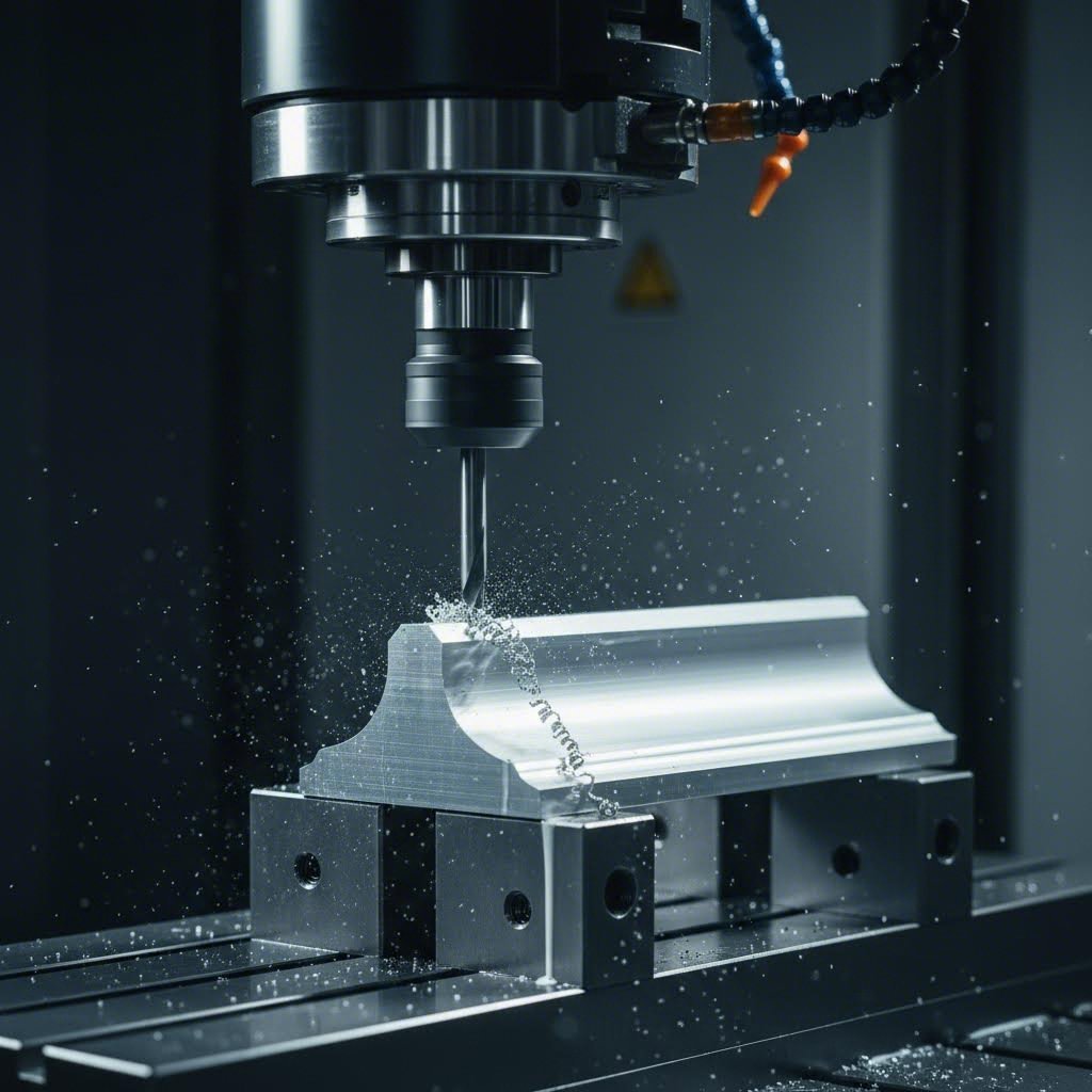
Why does CNC machining matter more for airfoil profiles than for standard rectangular extrusions? The answer comes down to clamping and referencing. When you secure a flat-faced channel or angle in a vise, the flat surfaces provide stable contact points. The workpiece sits predictably, and the machine knows exactly where the material is relative to the cutting tool.
Airfoil profiles have no flat faces. Every surface curves or tapers, which makes clamping more complex and introduces the risk of the profile shifting during machining. CNC machines follow computer programs exactly, maintaining tight tolerances that manual operations struggle to achieve on these challenging geometries.
The precision advantage becomes critical when you need consistent hole positioning across a production batch. Imagine installing 200 airfoil blades into a louver frame. If the mounting holes vary by even a millimeter from blade to blade, assembly becomes a nightmare of forced fit-ups and misaligned connections. CNC drilling keeps spacing and depth consistent across all parts, which is essential for large production runs where every blade must be interchangeable.
Typical CNC tolerances for aluminum parts range from approximately ±0.01 mm to ±0.05 mm. This level of precision ensures that aluminum extrusion brackets, end caps, and pivot hardware fit correctly without adjustment. Manual machining depends on operator skill, introducing variability that compounds across hundreds of parts.
For cutting aluminum extrusion profiles to length, CNC saws deliver clean, accurate cuts that reduce gaps during assembly. Miter cuts for frame corners require even tighter control because angular errors multiply when four corners come together. A half-degree error on each miter becomes a two-degree frame distortion that may prevent proper closure.
Beyond basic cutting and drilling, CNC milling creates slots, pockets, and channels for aluminum extrusion accessories like cable management, LED strips, or panel mounting hardware. These features would be difficult or impossible to produce consistently with manual tools, especially on curved surfaces where tool access angles change continuously.
How do airfoil blades actually connect to their supporting frames? Three primary methods dominate louver and facade assemblies:
End brackets attach to the blade tips and mount into the frame rails. This approach works well for fixed-blade systems where the airfoil profiles don't need to rotate. The brackets typically bolt or clip into channels in the frame, and consistent hole positioning on the blades ensures every bracket aligns correctly.
Pivot pins allow blades to rotate for adjustable louver systems. The pins pass through holes at each blade end and seat into bearings or bushings in the frame. Here, hole diameter and position tolerances become critical because any variation affects how smoothly the blade rotates and whether it binds at certain angles.
Welded connections provide the strongest attachment for structural applications but require careful heat management to avoid distorting the airfoil geometry. Welding also affects the finish in the heat-affected zone, so welded assemblies typically receive their final coating after fabrication rather than before.
Why does consistent hole positioning matter so much? Consider a louver system with 50 blades. If the end bracket holes are accurately positioned on every blade, assembly proceeds quickly because each blade drops into place without adjustment. If hole positions vary, installers must force some blades into position, which stresses the brackets and frame, or reject blades that won't fit, which delays the project and increases waste.
Once installed, airfoil profiles in louver and facade systems require periodic maintenance to preserve their appearance and function. Anodized finishes should be cleaned using mild soap solutions to retain their original beauty. Products safe for bare hands, including most commercial cleaning products, work well. Apply the cleaning solution with a soft cloth, sponge, or brush, and avoid strong acid or alkali cleaners that can damage the oxide layer.
PVDF-coated profiles follow similar cleaning protocols. The fluoropolymer finish resists most environmental contaminants, but periodic washing removes accumulated dirt before it can affect appearance. In coastal regions or industrial areas, more frequent cleaning may be necessary because atmospheric salts and pollutants adhere more tenaciously.
One design consideration often overlooked at specification stage: access for cleaning. Louver systems on high-rise facades require scaffolding or rope access for maintenance. If blade spacing is too tight or frame geometry blocks access to certain surfaces, cleaning becomes impractical and the finish degrades faster in those areas. Recessed and sheltered sections typically become more heavily soiled because they lack the natural rain-washing that exposed surfaces receive.
The cleaning schedule should integrate with other building maintenance for efficiency. Both glass and aluminum curtain wall components can often be cleaned simultaneously, reducing access costs and ensuring consistent appearance across the facade.
With fabrication and assembly considerations addressed, the final step is navigating the specification and sourcing process to turn your requirements into a purchase order.
You've defined your geometry, selected your alloy and temper, chosen a surface finish, and mapped everything to your application requirements. Now comes the part that turns all that specification work into actual profiles arriving at your facility: sourcing. This step trips up many buyers because the aluminum extrusion market operates differently than commodity purchasing. Understanding the decision sequence from concept to purchase order helps you avoid costly missteps and find the right aluminum extrusion supplier for your project.
Here's the six-step process that experienced specifiers follow:
Let's walk through each step so you know exactly what to prepare before contacting aluminum extrusion companies.
Before reaching out to any aluminum extrusion manufacturer, you need a complete technical package. Vague requests like "we need an airfoil shape for a louver system" waste everyone's time and generate quotes that don't reflect your actual requirements.
Your specification package should include:
The more complete your specification, the more accurate your quotes will be. Suppliers who receive incomplete requests either pad their pricing to cover unknowns or come back with clarifying questions that delay the process.
Here's where the standard-versus-custom decision becomes critical. If your geometric requirements can be met by an existing catalog profile, you'll save significantly on tooling cost and lead time. Standard profiles are pre-designed shapes commonly used across industries, offering lower cost and faster delivery. Custom extrusion aluminum profiles require new die development, which adds both cost and time.
When does custom tooling make sense? The crossover point depends on volume and performance requirements. If you need 500 kg of a profile that's close to a standard shape, modifying your design to fit the existing die usually makes economic sense. If you need 5,000 kg and the standard profile compromises your shading performance or assembly fit-up, custom tooling pays for itself through better product performance and reduced field adjustments.
For airfoil profiles specifically, standard options are limited because the geometry varies so much by application. Most architectural louver and facade projects end up requiring custom dies. The good news? Aluminum extrusion tooling costs are generally much lower than alternative technologies like die-casting or steel roll forming.
Once you've identified potential aluminum extrusion suppliers, the qualification process begins. This step separates reliable partners from vendors who overpromise and underdeliver. Here's what to request:
Die ownership terms matter more than most buyers realize. Who owns the die after you've paid for it? Can you take it to another supplier if the relationship doesn't work out? Some manufacturers retain die ownership regardless of who paid for tooling. Others transfer ownership after full payment but charge storage fees for dies held between orders. Clarify these terms upfront to protect your tooling investment.
Tolerance certifications demonstrate whether the supplier can actually hold the dimensions you've specified. Ask for inspection reports from similar profiles they've produced. Leading suppliers maintain dimensional tolerances within ±0.1 mm and provide mill test certificates with every shipment.
Finish test reports verify coating performance claims. For anodized profiles, request oxide thickness measurements and salt spray test results. For powder coating, ask for adhesion test data and coating thickness verification. For PVDF, request UV exposure test results and color retention data. Reputable aluminum extrusion manufacturers issue these reports routinely, not just upon request.
Sample lead time tells you how quickly the supplier can produce evaluation parts. Using existing dies, samples typically take 7-15 days. Custom tooling adds 10-20 days for die fabrication before sample production can begin. If a supplier promises faster turnaround than these benchmarks, ask how they'll achieve it.
Production capacity determines whether the supplier can scale with your needs. Evaluate their press tonnage range, number of extrusion lines, and in-house finishing capabilities. Vertically integrated manufacturers like Shengxin Aluminium, with 35 extrusion presses ranging from 600T to 5500T and end-to-end support from die development through surface finishing, represent the type of partner that can support your full specification journey from prototype die to mass production with consistent quality.
Quality certifications provide baseline assurance. At minimum, look for ISO 9001 certification. For automotive or aerospace applications, certifications like IATF 16949 or AS9100 may be required. These standards verify process control, traceability, and continuous improvement practices.
Before committing to a full production order, request physical samples to validate extrusion precision, surface finish, and material consistency. This sample validation phase is your opportunity to catch problems before they affect hundreds or thousands of parts.
Minimum order quantities exist for good reasons, even when they seem inconvenient for small projects. MOQs reflect the economics of die preparation, press setup, and quality verification that occur regardless of order size.
Several factors influence MOQ requirements:
For standard profiles, MOQs often start around 500 kg per item. Custom dies may carry 1,000-2,000 kg MOQs to amortize tooling costs across a reasonable production volume. However, some suppliers offer sample runs from as low as 1 kg for evaluation purposes, which helps you validate the profile before committing to production quantities.
Lead time breaks down into three components. Tooling lead time covers die fabrication, which averages 2-4 weeks depending on complexity. Extrusion lead time covers actual production once the die is ready, typically 1-2 weeks depending on schedule position. Fabrication lead time adds time for secondary operations and finishing, potentially adding days or weeks depending on complexity.
For repeat orders using existing dies, lead times compress significantly because tooling is already available. Expect 7-15 days for samples and 20-35 days for bulk production post-approval. New die orders should budget 4-6 weeks minimum from order to first delivery.
Payment terms typically follow a staged structure. Standard terms include 30% deposit with 70% against bill of lading. For first-time orders, consider using escrow services to protect both parties. High-volume partners may qualify for net-30 terms after establishing a track record of successful deliveries.
One final consideration: die storage and reuse. Confirm the supplier's policy for storing your die between orders and any fees associated with reactivating production after extended gaps. This protects your tooling investment and ensures you can reorder without starting from scratch.
The aluminum extrusion news cycle regularly highlights supply chain disruptions and capacity constraints affecting the broader aluminum extrusion market. Building relationships with capable, vertically integrated suppliers before you need emergency capacity gives you options when market conditions tighten. A proactive sourcing approach today helps secure a resilient supply chain for your airfoil profile needs tomorrow.
An aluminum airfoil extrusion is a continuous profile with an aerodynamic cross-section featuring a curved leading edge, tapered trailing edge, and defined chord length. Unlike standard structural extrusions such as angles or channels designed for load-bearing, airfoil profiles are optimized for airflow management, solar shading, and aesthetic blade effects. The terms airfoil, aerofoil, wing profile, and blade extrusion all refer to this same product category with regional naming variations.
Tooling cost depends on profile complexity, tongue ratio, chord length, and camber ratio. Simple solid airfoils cost less to tool than hollow profiles with internal webs or T-slots. High tongue ratios increase die stress and limit minimum wall thickness. Longer chord lengths require larger dies and higher press tonnage. Pronounced camber adds complexity due to asymmetric metal flow paths. Keeping wall thickness variation below 2:1 and tongue ratios under 3:1 helps control costs.
PVDF coating is the premium choice for coastal or high-UV environments. This fluoropolymer finish offers exceptional UV resistance, superior salt spray performance exceeding 2000 hours, and outstanding color stability over decades. While it costs more than anodizing or powder coating, PVDF maintains color integrity with minimal chalking even after years of harsh exposure, making it ideal for facade applications where long-term appearance matters.
Your specification package should include a dimensioned cross-section drawing with chord length, maximum depth, wall thicknesses, and edge radii. Also specify tolerance requirements for critical dimensions, alloy and temper designation like 6063-T5 or 6061-T6, surface finish with color and performance requirements, cut lengths, quantity estimates, and any secondary operations needed. Complete specifications generate more accurate quotes and faster turnaround from suppliers like Shengxin Aluminium.
T5 temper suits architectural and decorative applications where appearance matters more than structural performance, offering lower cost and faster production. T6 provides significantly higher strength for structural loads or demanding service conditions but costs more with longer lead times. T52 offers excellent dimensional stability through stress-relief stretching, making it ideal for precision assemblies and curtain wall systems where tight tolerances and long-term straightness are critical.


 Servicio en línea
 0086 136 3563 2360
 sales@sxalu.com
 +86 136 3563 2360
 español
 English
 français
 Deutsch
 русский
 português
 العربية
 ไทย
ไทย Việt
Việt Українська